
|
|
Forum Index : Electronics : Hopefully? Another 48vdc-240vac Toriod Inverter build.
| Author | Message | ||||
| KeepIS Guru Joined: 13/10/2014 Location: AustraliaPosts: 1405 |
More pretesting while it rains, stopping me from changing one of the solar banks over to 55V. The de-soldering station heat gun causes the LED fluros to flicker, looking at the load shows the gun drawing 530 watts and turning it on and off a few times a second. It looks like the Chinese driver has trouble regulation under that condition. I guess some of this will be answered when I build the new Driver board. Perhaps it's just the nature of a Transformer design? Not a problem though as it just seems bullet proof at the moment. Has anyone noticed flickering (LED lights) when loads of 500 watts are switched on and off a couple of times per second? Started the 3HP Dust extractor a few times, it draws 49 Amps from the inverter AC output and drops the AC from 230v to 200v during the sustained high current 3 to 4 second startup. AC waveform looks good, you would not know that 10kW had been switched on from the sound of the inverter. BTW that load was while the house and Workshop are running off the inverter. Some of this voltage drop would be in the mains Filter and cabling. So almost 10kW extra draw on the AC side, very little noise from the Toriod and the Silicon iron chokes as usual, were silent. . Edited 2023-02-21 12:18 by KeepIS It's all too hard. Mike. |
||||
| analog8484 Regular Member Joined: 11/11/2021 Location: United StatesPosts: 92 |
The problem is unlikely unique to the Chinese driver. I doubt the nanoverter (or another backshed inverter) could do much better. The problem is likely due to the fact that the inverter control loop only updates once (or twice) per mains cycle and that's just not fast enough to compensate for significant non-linear loads like what you have observed. |
||||
| KeepIS Guru Joined: 13/10/2014 Location: AustraliaPosts: 1405 |
Yes, the last few days running seem to confirm this, and logically thinking about it, a straight 400vdc to 240AC converter has no transformer to contend with. That was my old inverter, and no led flicker on high pulsing loads, however, with more load on the new toriod inverter, the led lights stop that very slight flicker on that type of high pulse load. It's all too hard. Mike. |
||||
| wiseguy Guru Joined: 21/06/2018 Location: AustraliaPosts: 1018 |
Expanding on Analog's comments, if there is a 5kW load on the inverter and you add some extra 500W pulsing load it represents somewhere between a 0 and 10% change. If you add the same load to an unloaded inverter idling at 17W it represents somewhere between a 0 and 3000% change. The feedback system and delays and damping can all affect the system stability. Being overdamped or underdamped can cause these sort of issues. The damping issues can cause undershoot and overshoot of the output voltage as it tries to cope with the load/unload issues and I suspect this may well be the cause of the flickering lights. If you get to use the EG8010 with the active rectifier and AC output that corrects on a cycle by cycle basis this might just go away or be greatly reduced, I will be most interested in the comparison results if/when you have it up and going. If there is a filter capacitor setting an average DC level for the feedback loop, it is not really responding to the last update of a cycle but an integrated/delayed result of multiple previous updates. For instance a 10u capacitor into a 10K pot load after a rectifier has a single (discharge) time constant of 100millisecs, in other words an integration of the last ~5 mains cycles. Edited 2023-02-24 16:05 by wiseguy If at first you dont succeed, I suggest you avoid sky diving.... Cheers Mike |
||||
| KeepIS Guru Joined: 13/10/2014 Location: AustraliaPosts: 1405 |
Mike, I was thinking the same thing after reading your insight into the filter design and rational behind same during your posts. I'm documenting everything I notice on this test unit so I can see what actually changes with a slightly different and way better design IMHO. Even if the new driver boards only preforms the same as the current China unit, I'll still be over the moon as I will have a design with a full set of spares, and one that I can repair easily if the worst case happens. BTW: I have all the Solar panels and controllers running at 55 volts now. The test inverter is in a cabinet installed in service and running everything. Dam it's so quite, cool running and with the low idle current I'm just blown away with how well this has turned out. I've got to clean up the shed, got a week of yard chores (work) to do, and then I will be straight into the new Inverter driver build, this to me is the fun part. All that hard work has been done. . It's all too hard. Mike. |
||||
| Godoh Guru Joined: 26/09/2020 Location: AustraliaPosts: 387 |
I have found that my 8010 based inverters don't like switched loads. They definitely don't like a heat gun on low setting, high is fine, but whatever the heat gun uses to switch to low caused much humming. I have a benchtop oven/air fryer, it had some sort of electronic switching of the elements too, the inverters did not like it. If I turned it up it caused the inverter to go into overload. My solution was to discard all the electronic stuff, put a switch in that turned on the upper or lower elements, a switch for the fan and a thermostat. The inverter has no problems with it now. I am guessing it is much the same as is being discussed in this thread. It seems that pulsing loads are seen as large loads. Pete |
||||
| KeepIS Guru Joined: 13/10/2014 Location: AustraliaPosts: 1405 |
Hi Pete, a few pages back we discussed the reason some heat guns distort the AC waveform. Mine will run the heat gun on low, it just growls a bit reflecting the half rectified distortion caused by sh*t Heat guns using a Diode in series with the Heater element for Low heat setting. Nothing else really bothers this inverter, that includes starting machinery that draws 14Kw on startup. Another unit draws over 10kW for almost 5 seconds as it spins up. The inverter is virtually silent in all these cases. The only other equipment that causes a "slight hum" is a BIG switching UPS that runs 4 computers and 6 big screens. It runs the Air conditioners, Clothes drier, Washing machine, 1.8kW Multi oven Air-Fryer, espresso Coffee machine, huge Microwave, Inverter fridge freezer, small standard chest freezer, mains pressure water pump, 2.5hp band saw, huge bench grinder and the endless number of workshop equipment, all like they are on full mains. We are close to being totally off grid including 240vac electric Hot water system fed directly from solar panels. It's all too hard. Mike. |
||||
| analog8484 Regular Member Joined: 11/11/2021 Location: United StatesPosts: 92 |
That's definitely one issue with inverters with slow control update rates. Phase-cut non-linear loads like heat guns on low setting are bad but at least they don't have significant reactive current. I have seen some non-linear loads with significant reactive current pulses do crazy things to inverters. It has given me new appreciation for how well the grid handles these loads. |
||||
| KeepIS Guru Joined: 13/10/2014 Location: AustraliaPosts: 1405 |
I wanted a High Current Relay to automate the cold startup when connecting the Battery bank to the inverter when the inverter caps are discharged. The price is a bit crazy on most but I found this unit a week to two ago for $55.00. RELAY LINK 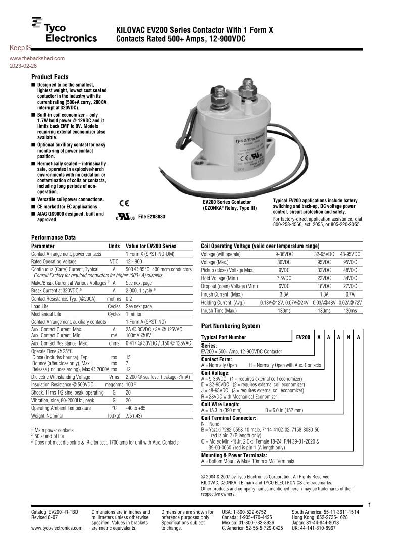 There were no 48 volt units available when I ordered, so I had to settle on the 12 to 24 (36v) unit. These have a built in economizer and are supposedly rated at 500A. Took a chance, ordered one, it arrived today. Quick test shows around 60mA @ 24V holding current, great. I wanted to use this now and grabbed a spare 240vac to 24v 3A power brick out of the parts bin. Power Pack turns on at 44 VDC and Relay energizes. Relay / power pack drop out at 17 VDC. Idle current with relay driven by power brick @ 55V is 50mA, 2.7 Watts holding current for a big Solenoid, I can live with that. So this takes care of the CAP charge timing with the relay not energizing until caps are at 44VDC. I wired a 47 ohm resistor in series with the momentary push button switch I had installed on the front panel and connected it across the Big Relay contacts. Worked perfectly, but, I had to reduce the Charge resistor to 10 Ohms to stop the Relay grabbing and releasing about 4 times before it locked on. As soon as it did that the first time I realized the 47 ohm resistor could not supply enough current to power the 240VAC brick right at its switch on point, 44 VDC, even though the caps were at the same voltage voltage. The 10 ohm resistor is fine as the maximum inrush current is still limited to 5.5A to the Caps. This is a really Nice looking unit, beautiful build quality, nice an heavy and dam does it thump in on startup. I no longer have to worry about remembering to precharge the inverter caps if the battery bank is switched Off for any reason. BTW I know Mikes (wiseguy) new Inverter board design I'm building has the logic and economizer on board for driving a big relay. More importantly, if I'm not here, my Wife can't make a mistake as it's all automated now. Edited 2023-02-28 16:26 by KeepIS It's all too hard. Mike. |
||||
| phil99 Guru Joined: 11/02/2018 Location: AustraliaPosts: 1815 |
This info is a bit late for you but a high current relay can be made (if speed isn't an issue) from a battery isolator switch and a model servo motor. Control it with a PWM signal. A bit cheaper and almost no holding current. |
||||
| KeepIS Guru Joined: 13/10/2014 Location: AustraliaPosts: 1405 |
This is true but not as compact. I've done things like that many times but I normally use stepper motors as I have many sized units. In this build I wanted a compact fully sealed unit specifically designed for this purpose, I am expecting zero issues with this. It's all too hard. Mike. |
||||
| KeepIS Guru Joined: 13/10/2014 Location: AustraliaPosts: 1405 |
RH Scale Current and Volts, Current in Amps. We had just powered up some Big Wood working equipment and once it was running I switched the ATS back to "Mains Priority" just before the 14 minute mark. Everything shut down and then restarted, I thought the worst [Inverter], my wife restarted the Wood working equipment thinking it was now on mains, and before I had realized that it was the MAINS that had tripped and the Inverter had switched back in, hence two more double 13.3kW peaks on the Inverter Log graph. BTW the earlier peaks at 2 minutes were from me doing some testing with the same two pieces of equipment. Why both mains "current trip" units tripped when the ATS switched over to mains I don't know, one Switch is in the Shed Fuse box and the other in the Main supply fuse Box for the shed Feed. 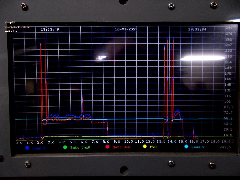 FYI the Inverter DC input Isolater / Pre-charge solenoid I posted about is just magic, I can't really measure any voltage drop across it. Been overcast dim and raining all day here . Edited 2023-03-10 16:16 by KeepIS It's all too hard. Mike. |
||||
| tinyt Guru Joined: 12/11/2017 Location: United StatesPosts: 431 |
This is still on paper and copper but not yet assembled for testing. 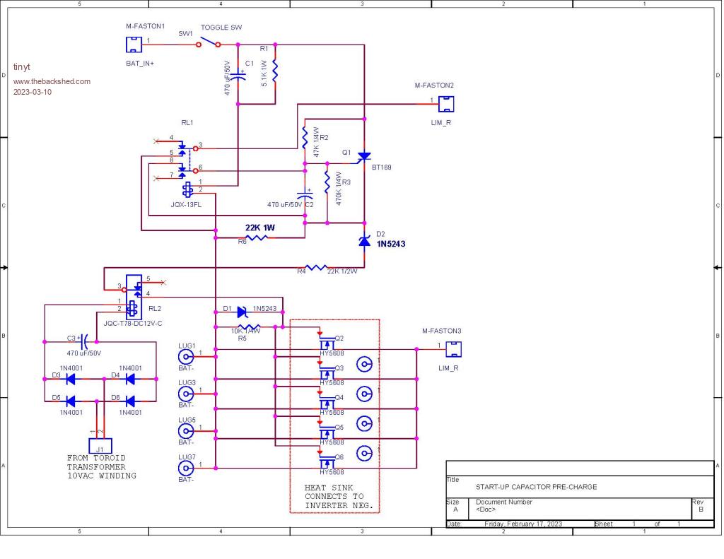 The pre-charge resistor will be between the two LIM_R connectors. In theory SW1 can be left on and if BAT power re-cycles, it will also re-cycle. Edited 2023-03-11 00:13 by tinyt |
||||
| KeepIS Guru Joined: 13/10/2014 Location: AustraliaPosts: 1405 |
Looks good, in the past I would have gone in that direction, and I almost did. However in light of current circumstances (global and personal) I am doing everything with this off grid build to keep it simple, I may not be around to repair it if it fails. Apology for the quick sketch of the circuit. 1: This Contactor is just beautiful quality with a very small footprint. 2: The terminals are very robust and of high quality. 3: All I needed to completely automate the Power up / Power down cycle was a single 3 position switch and an old 240vac -> 24vdc plug pack. The following simple circuit is foolproof. You cannot catch it out. I had the 3 pole 3 position switch in the parts bin along with the plug pack. The Batteries are only connected to the the inverter when inverter caps are charged to 44 volts, takes around 1 second. The plug pack holds power to the Contactor down to 17vdc input (very low hold current) Best of all, I have a bin full of plug Packs, I have a spare Contactor and switch. If this ever fails (unlikely) it's a few seconds to repair for me and someone not so clued up should have no trouble diagnosing and repairing that part of the inverter. So one switch to Connect / Disconnect the Battery's, leave it in standby or run, and it can auto start if required from any state including off. At the moment it only auto starts if it's in Standby. As the inverter is running 24/7 the auto start is hardly ever used. 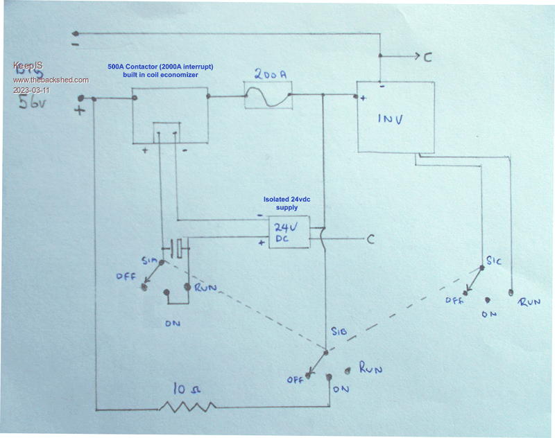 . Edited 2023-03-11 12:26 by KeepIS It's all too hard. Mike. |
||||
| KeepIS Guru Joined: 13/10/2014 Location: AustraliaPosts: 1405 |
This does exactly that: If it's running and you disconnect the batteries, the Contactor drops our "after" the Inverter caps have discharged down to 17v, which means that the inverter itself has already turned off due to Low battery voltage detection. If you then reconnect the batteries, the inverter powers up almost instantly with no spark or high inrush current, just a loud clunk as the contactor pulls in when caps reach 44v. In my case I have 350A isolation switches on each Battery bank, so no more switch jamming due to a partly fused contacts when I forget to disconnect the inverter or precharge the caps. In my system, even if the inverter was on, the Load will not be reconnected until the Inverter AC output had reached 190 VAC AND the Battery voltage is above the minimum set value. . Edited 2023-03-11 13:39 by KeepIS It's all too hard. Mike. |
||||
| Murphy's friend Guru Joined: 04/10/2019 Location: AustraliaPosts: 602 |
Hmmmm, What happens if that 200A fuse trips for any reason? No auto start I assume? I have gone the other way, my inverter has the 5V power to the Nano controlled by voltage sensing the capacitors. Not possible to turn it on (manual switch) unless the caps are charged. Disconnecting & re connecting it from the batteries is an entirely other matter. I would not want anybody who does not understand how this inverter works to do that. I really see no need for doing that unless some repairs are required. With my set up the initial inrush is limited by bypassing the manual DC power switch (instead of your fancy contactor  ) with a 15R hi watt resistor. Once the voltage sensing tells me the caps are charged, I short that resistor with the switch. It's now ready to turn the electronics ON. ) with a 15R hi watt resistor. Once the voltage sensing tells me the caps are charged, I short that resistor with the switch. It's now ready to turn the electronics ON.Should the inverter trip out for any reason, I have a spare inverter ready and connected to the batteries, caps fully charged, just need to swap over the AC output plug and turn that inverter ON once the tripping reason was investigated & fixed. I'm not sure if it's such a good idea to automate any of this. If there is a fault and the inverter shuts down, I would prefer the fault is found and rectified before attempting to re start the inverter. My inverter has been running un attended for over 4 weeks in a row while I was away, with no problems. It was powering two fridges and any electronic equipment on standby. Had it shut down I would accept the spoilage of whatever was left in the fridge, much preferable than having a fire resulting from a possible electrical fault and nobody in attendance to take care of that. |
||||
| KeepIS Guru Joined: 13/10/2014 Location: AustraliaPosts: 1405 |
Well I still use a 10 ohm resistor that bypass the OPEN contactor to charge the caps, the only difference is the contactor automatically shorts the resistor at 44v charge. If the 200A fuse goes then we have a bigger problem somewhere, it would take around 300A for more than a few seconds to blow that fuse, and of course I would not want to have this thing start if that fuse went. Yes understand the Nano setup, but likewise, it's not possible to turn this inverter on unless the caps are charged. We are thinking along the same lines, I have a spare inverter driver that takes all of 2 minutes to swap over, no need to have the caps charged though I'm going a bit overboard in that I'm about to start on wiseguys design and will have a third inverter driver, as you know this was supposed to be my test inverter driver board to get the toriod, chokes and the cabinet sorted, and to get a feel for what not to do to an inverter. However it appears to be almost indestructible so far with over 13kW start loads many times a day most day of the week. If there is a fault, the inverter will not start. This system has an ATS and I can select Mains or Solar priority, therefore it must be able auto start if it's set to Mains priority, perhaps the term Auto start is misinterpreted, I mean it can be off or in standby and controlled to start if / when the Mains fails, when Mains power returns it will go back to its previous state. Once I am off grid completely, of course it won't do that. Obviously if set to Solar priority, the ATS will only switch to Mains if the Inverter stops for some reason. I have 3 sets of batteries, each bank has its own big disconnect switch and is fused, each bank has its own charge controller and solar panels, normally all banks run in parallel. There may be times when you want to save one bank from discharging, or have a problem in one bank. This system is designed for that, I have written a complete manual with full instructions in case that need ever arises and I'm not here. Many thing we take for granted are going to change in the near future and I'm trying to make sure this system can be kept running in some fashion no matter what for as long a possible. It's all too hard. Mike. |
||||
| Murphy's friend Guru Joined: 04/10/2019 Location: AustraliaPosts: 602 |
You'd do well using Wiseguy's driver design - I'm using it too but I left out a few of the parts he shows on his schematic and it works just as well. I think that old madness PCB that still gets ordered is not as reliable as wiseguy's opto isolated driver type and the better totem pole transistors on that. I see you still use mains power, I run off grid but can manually switch over to street mains if all else fails ( not going to happen   ). ).Fortunately our premier has given us oldies an energy supplement payment which will cover my street power connection fees for the next 10 years since my meter reads zero power consumption on each bill. I'm no good with acronyms, what's an ATS? |
||||
| phil99 Guru Joined: 11/02/2018 Location: AustraliaPosts: 1815 |
"I'm no good with acronyms, what's an ATS?" Ditto usually, but this one is Automatic Transfer Switch. |
||||
| KeepIS Guru Joined: 13/10/2014 Location: AustraliaPosts: 1405 |
Yes, ATS = Automatic Transfer Switch - obviously handles the power source switching between Mains or Solar power to the property. I agree with your thoughts on Wiseguy's design, I really do like it, I have everything ready to build it and I'm really looking forward to starting on it. The nice thing is that it will just slot straight into the Inverter cabinet with virtually no changes to be made. However I have to clean up the Workshop and take a load of horded crap to the tip before I can start. I had some good news for a change, my Heart efficiency has gone from 47% back up to 70% (11 months since two heart attacks) so all the effort and walking for an hour every day, no mater how bad I felt and in rain, shine and blizzard has not been in vain, they seem to think I will get lot higher, so I'm feeling a bit more positive. I was lucky in a sense as fast walking for a hour or more every day was the normal daily routine for me. Yes the energy supplement pays for the exorbitant supply charge. I've mentioned before that our old "still running" solar feed in array is pumping into the grid and covering connection cost and more. As soon as they take that away, or try to charge us for feeding power into the grid, it will be disconnected and added to the solar for total off grid running. In the meantime I take advantage of the feed in. It's all too hard. Mike. |
||||
