
|
|
Forum Index : Microcontroller and PC projects : New PicoMite firmware release V5.07.06
| Author | Message | ||||
| matherp Guru Joined: 11/12/2012 Location: United KingdomPosts: 10273 |
OK got that one working - once I have the TX version I'll post a beta |
||||
| Bleep Guru Joined: 09/01/2022 Location: United KingdomPosts: 625 |
Hi Peter, Thanks, yes that is understood, except I'm having to output 225 words or more, at a rate of 37uS per word, (approx 8.5mS for all the data), otherwise the fifo will run out of data, so the Basic is struggling to keep up, there is however large pauses in between each burst for processing, I will however try using the interrupt when available. Thanks for your continuing support. Regards Kevin. |
||||
| matherp Guru Joined: 11/12/2012 Location: United KingdomPosts: 10273 |
if you OR (1<<30) to SHIFTCTRL then you will get an 8 word TX FIFO instead of 4 which might help |
||||
| Volhout Guru Joined: 05/03/2018 Location: NetherlandsPosts: 5072 |
That is why I suggested FSTAT, since it takes the result of the FIFO fulleness check against the set fullness level. Should (have not tested yet) also work with linked fifo's. Volhout PicomiteVGA PETSCII ROBOTS |
||||
| Volhout Guru Joined: 05/03/2018 Location: NetherlandsPosts: 5072 |
Hi Peter, I have tried to put together something that along the lines of my thinking. I have not been able to "debug" this. The PIO code works, but i have not written a "interrupt replacement by polling". If you have problems, I will look into that tonight. The PULL in the PIO code is non-blocking, since the code will follow the GP0 clock, and will not wait. Easier for debug. ' demo program to demonstrate the use of the PIO interrupt ' the PIO is programmed to pull 1 word from FIFO at every rising edge of the GP0 pin. ' the GP0 pin is controlled from MMBasic in this demo, but could also be driven from ' an external source. � '-------------------------------- PIO state machine ----------------------------------- � 'PIO clear �pio clear 1 � 'the PIO program 'address � �code � �mnemonics � � � � comment ' �0 � � �2000 � � �WAIT GP0=0 ' �1 � � �2080 � � �WAIT GP0=1 ' �2 � � �8080 � � �PULL noblock ' �3 � � �0000 � � �JMP 0 � 'program pio1 �pio program line 1,0,&h2000 �pio program line 1,1,&h2080 �pio program line 1,2,&h8080 �PIO program line 1,3,&h0000 � 'write the configuration, running 100kHz (data in FIFO pulled 10us after rising edge GP0) �PIO init machine 1,0,1e5,0,,,0 � � � '-------------------------------- MMBasic MAIN --------------------------------------- � 'Halt the PIO from GP0 from MMBasic before it fills the FIFO out of control �setpin gp0,dout �pin(gp0)=0 � 'variables �dim size%=10 �dim d%(size%)'=(....) fill with data �dim pointer%=0 �'points to first array cell �dim repeat%=0 � '0=do we stop, 1=repeat sending data �dim ready%=0 � �'0=running, 1=we are done... � 'start the pio1 code, state machine 1.0 will be waiting for a rising edge on the GP0 pin 'then it will pull 1 word from fifo. Then it will wait for the falling edge. The cycle repeats. �PIO start 1,0 � 'interrupt format PIO INTERRUPT PIO,SM,RX_SUB,TX_SUB �PIO interrupt 1,0,OFF,FeedFifo � 'freguently PIO pull data from the fifo �Settick 100,PullFifo � 'Main: check if data transfer is ready, when yes, then stop interrupt �do � �if ready%=1 then � � �print "done, stop PIO" � � �pio stop 1,0 � �else � � �print "still running" � �end if � �pause 200 �loop � � � '----------------------------------- SUBS --------------------------------------- � 'in this sub write 1 word to the Fifo. We can expand that to write more data until 'the fifo is full by repeated write and check of the fifo full flag. SUB FeedFifo �PIO write 1,0,1,d%(pointer%) �inc pointer%,1 �if pointer%=size% then � �if repeat%=1 then � � �pointer%=0 � �else � � �ready%=1 � � �pio interrupt 1,0,off,off 'stop interrupt � �end if �end if end sub � 'in this sub we toggle the GP0 pin to force the PIO to fetch data from the FIFO sub PullFifo �pin(gp0)=1:pause 1:pin(gp0)=0:pause 1 end sub � � Thank you for your help. Really appreciated. Volhout Edited 2023-01-13 22:33 by Volhout PicomiteVGA PETSCII ROBOTS |
||||
| Bleep Guru Joined: 09/01/2022 Location: United KingdomPosts: 625 |
HiPeter, I've been looking at how to join the Rx & Tx buffers to create a unified Tx FiFo, thanks for the info, I notice you have added this feature officially, in the latest release :-) I'll now 'have' to try using the new interrupt triggered refilling of my now longer FiFo, see if Basic can respond fast enough, should be an interesting challenge. ;-) Thank you again. :-) Regards Kevin. |
||||
| Mixtel90 Guru Joined: 05/10/2019 Location: United KingdomPosts: 7889 |
The "interesting challenge" comes when you use the second CPU core of the non-VGA version to DMA the data. :) Mick Zilog Inside! nascom.info for Nascom & Gemini Preliminary MMBasic docs & my PCB designs |
||||
| stanleyella Guru Joined: 25/06/2022 Location: United KingdomPosts: 2548 |
Would that make spi , i2c displays faster for example, being non vga and the other core doing nothing? |
||||
| Mixtel90 Guru Joined: 05/10/2019 Location: United KingdomPosts: 7889 |
No. With any serial display you are limited by the clock speed that's clocking the data - at both ends of the link. Even if you can send blindingly fast it doesn't mean that the other end can keep up. Transmission protocols will tell the fast transmitter to pause if necessary. Mick Zilog Inside! nascom.info for Nascom & Gemini Preliminary MMBasic docs & my PCB designs |
||||
| TheMonkeys Regular Member Joined: 15/12/2022 Location: AustraliaPosts: 59 |
Something I picked up this morning: cat tm$, ":" is tokenised to inc tm$, ":" with the appropriate error appearing when run. re-opening the saved script (before running) in the editor shows this change. This was in the previous (5.07.04) and seems to have persisted. I've only just downloaded/installed the new firmware and look forward to spending waaay too much time playing with the new toys.  |
||||
| matherp Guru Joined: 11/12/2012 Location: United KingdomPosts: 10273 |
cat and inc are the same command. There should be no error. Please post an example if you can demonstrate one |
||||
| TheMonkeys Regular Member Joined: 15/12/2022 Location: AustraliaPosts: 59 |
Now I'm confused. I was a) working under the assumption that the line of code was attempting to increment tm$ by ":". b) certain that there was an error. However, upon re-running the code this morning to confirm the error message, not only is there no error, but the code works as expected. Yes, "Cat" is still being replaced with "Inc".  *pulls head in* *pulls head in* |
||||
| vegipete Guru Joined: 29/01/2013 Location: CanadaPosts: 1129 |
Another polite request for both PicoMite manuals: Could the Real Time Clock Interface section include the Time$ and Date$ commands so that we know how an MMBasic program actually reads the date and time? Visit Vegipete's *Mite Library for cool programs. |
||||
| Mixtel90 Guru Joined: 05/10/2019 Location: United KingdomPosts: 7889 |
<A couple of updates - (UK time) 13:36, 15:00.> <More updates 22/1/23 09:12, 11:10> I've just got a few of these (16MB version) from Ali Express and they appear to be OK. Note that they are NOT 100% compatible with the Pico, but for my purposes that doesn't matter. Here are the differences that I've found: * The micro-USB connector is changed to USBC Hooray! :) * The SMPS has been replaced by a 3v3 linear regulator (ME6215). Beware the dissipation limit of this (250mW). This limits the *total* current to about 140mA from a 5V supply. This is to power both the PicoMite and any external loads. It also means that the input voltage must be at least 3.7V (at 200mA load) to be safe, a little lower at lower load. Not recommended for battery operation. * You can't disable the on-board SMPS as it hasn't got one - and there's no need to anyway as the major noise source has gone. * The 3V3EN pin becomes GP23, which is also connected to the WS2812 LED (if enabled - see below). * The ADC reference pin is on an additional 2-pin connector with a GND. The original VREF pin becomes ADC3. * VREF is floating and does not default to 3V3 unless you close a zero-ohm link, in which case it is directly connected. You could fit an 0603 size resistor here for more flexibility. * GP24 is connected to the USRKEY button. If the schematic is to be believed it pulls GP24 low via 10k. You can't use it to detect VBUS. (VBUS is no longer available on a pin). * VIN (pin 19) and VBUS from the USBC socket are connected via schottky diodes to V+ (Pin 20) and then via a fuse (unknown rating) to the regulator. VIN and V+ won't back-feed to the USB. V+ won't back-feed to either supply. * The WS2812 is disconnected unless you close a zero-ohm link. Once you do that, it's type "O", not type "B" and is on GP23. * The SWD connector now includes 3V3 so it's got 4 pins. The board is supplied with a 90-degree pin header for the SWD and the two 20-pin male pin headers. The Heartbeat LED is blue, so it's an obvious upgrade. :) This board doesn't have castellated connections so it's not suitable for surface mounting. :( �On the other hand, the connections are silk screened on both the top and the bottom of the board. ------- Currently running 5.07.07b7 Loaded first time. Have had no reconnect problems when reset or disconnected when using Tera Term. I've not been able to get the first sample to run at over 210MHz (non-VGA firnware). ------- I've looked at the possibility of using this on the PicoGame and it appears to have no problems. Simply configure the board as if you were using the SMPS and don't fit the regulator. This will mean breaking the 3V3EN link under the board. As it comes, pin compatibility isn't all that bad. The debug connector is the only real layout change. All ground pins are in the same places. Don't ground pin 37 (3V3EN, now GP23) Feed 5V into pin 39 as usual Get 3V3 out of pin 36 as usual (albeit at a slightly lower current) Connecting a LM4040 between pin 35 (VREF, now ADC3) will do no damage, but won't do anything else either! The only difficulty is if you want to use VREF. It's more awkward. You can always feed a reference voltage into ADC3 and use that to scale other inputs though. Circuit diagram: YD-2040-2022-V1.1-SCH.pdf 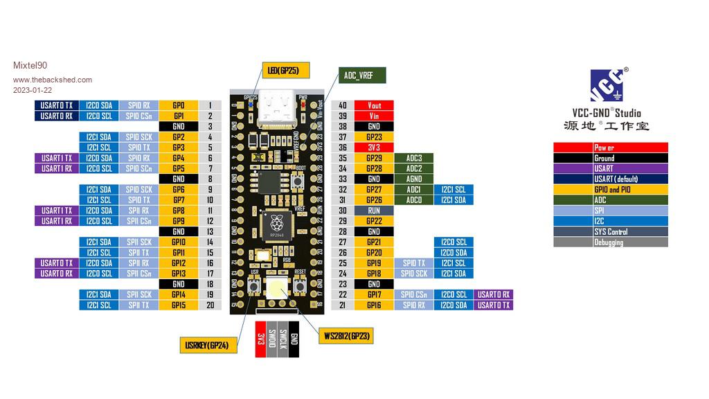 Edited 2023-01-22 21:14 by Mixtel90 Mick Zilog Inside! nascom.info for Nascom & Gemini Preliminary MMBasic docs & my PCB designs |
||||
TassyJim Guru Joined: 07/08/2011 Location: AustraliaPosts: 6271 |
Mine arrived today so your post was timely. My attempt at CPUSPEED 250000 also failed. I haven't tested all options but when I ran this program at 200000, the led flashed green bright once per cycle. at 133000, the led flashes white. With the faulty line of code changed to the commented out line, both speeds were the same. Because of the difference in operation at 200000, I will treat any speed increase with caution. ' DIM b%, n% =1, k% = 1 SETPIN GP23, DOUT DO BITBANG WS2812 O, GP23, 1, b% PAUSE 300 b% = RGB(n%,n%,n%) n% = n% + k% IF n% >= 32 THEN k% = -1 'if n% <= 1 then k% = 1 IF n% = 0 THEN k% = 1 ' this is the faulty line LOOP UNTIL INKEY$ <>"" BITBANG WS2812 O, GP23, 1, 0 I added a flying lead to the WS2812 instead of closing the link so I could use any IO for it. The same abnormality is observed when using another IO pin sometimes resulting in a different colour. Jim Edited 2023-01-23 12:27 by TassyJim VK7JH MMedit |
||||
| phil99 Guru Joined: 11/02/2018 Location: AustraliaPosts: 2626 |
Chip temperature might be a guide to the highest speed. My AliExpress Pico runs about 10C hotter than my ones with the RP logo at 378 MHz. > ? pin(temp) 46.70487386 > vs. genuine RP > ? pin(temp) 37.80809564 Edited 2023-01-23 13:54 by phil99 |
||||
| Mixtel90 Guru Joined: 05/10/2019 Location: United KingdomPosts: 7889 |
My own suspicion is that the speed limitation might be due to slower flash reading or access time. The RP2040 is probably the same chip - it probably isn't worth cloning them. That only leaves the clock oscillator and the flash - and China has a long history of producing both. The difference in temperature could possibly be down to whether the RP2040 package was bonded to the pcb prior to soldering and if so what with. Peter probably did the code for the WS2812 from the data sheet as the B version is more common. It may not have been tested with an actual O version until now - and there's no guarantee that the ones used on these boards are up to spec anyway. :) Still, for the price.... Mick Zilog Inside! nascom.info for Nascom & Gemini Preliminary MMBasic docs & my PCB designs |
||||
| matherp Guru Joined: 11/12/2012 Location: United KingdomPosts: 10273 |
Agree - this seems most likely I'm buying the Waveshare RP2040-Plus . More expensive but 100% pin compatible, 16MB, and rock solid at 378MHz PS: If is doesn't run at 252MHz try 378MHz. For the higher speed I halve the flash clock speed ( so 189MHz) whereas at 252MHz I don't Edited 2023-01-23 18:26 by matherp |
||||
| TassyJim Guru Joined: 07/08/2011 Location: AustraliaPosts: 6271 |
378MHz results in a lockup so it looks like I will be staying at ~180MHz for my units. That's not a problem, I rarely need the speed. I tested the onboard WS2812 on a 'normal' picomite. Having it on a fly-lead instead of closing the link came in handy. At 378MHz, the led showed the same flash of (usually) green when it should be off. Jim VK7JH MMedit |
||||
| matherp Guru Joined: 11/12/2012 Location: United KingdomPosts: 10273 |
Jim I assume this is the same? Works perfectly at 378MHz and with BITBANG WS2812 O,GP23,1,RGB(whatever). Sounds like you have them out of a duff batch. 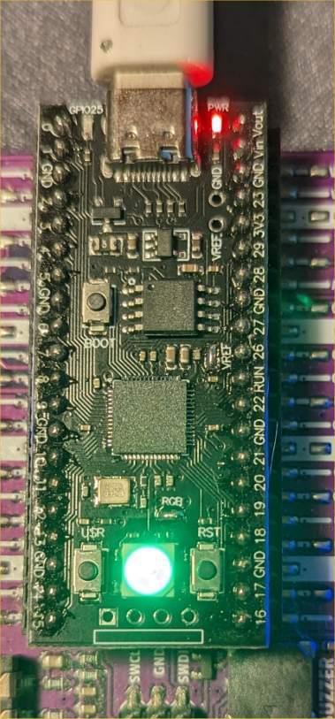 |
||||
| The Back Shed's forum code is written, and hosted, in Australia. | © JAQ Software 2025 |
