
|
|
Forum Index : Microcontroller and PC projects : Picomite(VGA) V5.07.07 betas - bug fixes + focus on PIO
| Author | Message | ||||
disco4now Guru Joined: 18/12/2014 Location: AustraliaPosts: 844 |
Library delete clearing main program. ------------------------------------- I checked the MM2 and it does NOT clear the main program on a Library delete. The Picomite can be made to work the same as the Library is in a separate block of Flash and can be erased separately. I had previously got the Library working on the F4 and there the Library is stored in the same Flash area as the main program and on delete only the whole area can be erased, so Program and Library both go. Easy fix to make it work like the Micromites. In the LIBRARY DELETE command we just need the comment out the last two lines which call the new command and add in the return; statement so it ends cleanly. return; // Clear Program Memory and also the Library at the end. //cmdline = ""; CurrentLinePtr = NULL; // keep the NEW command happy // cmd_new(); // delete any program,and the library code and return to the command prompt Latest F4 Latest H7 |
||||
| matherp Guru Joined: 11/12/2012 Location: United KingdomPosts: 8603 |
please ignore b31/b1 for the moment |
||||
| Volhout Guru Joined: 05/03/2018 Location: NetherlandsPosts: 3585 |
@Peter Tested on V50707b30 picomite (non-VGA) The picomite uses PWM for audio output. PWM=50% is no signal PWM varies between 0% and 100% (or 5% to 95%) when a tone is produced . The duty cycle is representative for the audio tone. PLAY TONE 1000,1000,50000 When tone output is stopped PLAY STOP The PWM's are not updated anymore with the audio modulation, but remain running at 44.1kHz. However.... The PWM's are stopped at the last value they had. If this is the top of a sinewave, the PWM is at 95% duty cycle. And there it is stopped. When this PWM duty cycle is demodulated (filtered) to audio, stopping the PWM results in a DC output voltage. When possible, I suggest to include a PWM=50% when stopping the audio tone. This returns the audio level to "no tone" voltage. Regards, Volhout P.S. This may as well contribute to clicking between notes played. Edited 2023-03-31 22:28 by Volhout PicomiteVGA PETSCII ROBOTS |
||||
| matherp Guru Joined: 11/12/2012 Location: United KingdomPosts: 8603 |
This is the change that actually stops the clicking between notes |
||||
| matherp Guru Joined: 11/12/2012 Location: United KingdomPosts: 8603 |
All OK again now V5.07.07b31 / WEB V5.07.07b1 https://geoffg.net/Downloads/picomite/PicoMite_Beta.zip |
||||
| Volhout Guru Joined: 05/03/2018 Location: NetherlandsPosts: 3585 |
Hi Peter, 95% there...... do play tone 1000,1000,2000 pause 1000 play stop pause 1000 loop You start tone for 2seconds, but cut it after 1 second with play stop. In 95% of the cases it returns to 50% PWM. In the remaining 5% it stops at the peak of the sinewave (for whatever unknown reason only that value). Attach the scope to the audio output and you will see the sine wave alternating with DC level. 95% of the time that is 50%, bot sometimes not. Volhout P.S. Maybe it is me, but F2 will not run the code from the editor. I need to press F2 2x (or F2, RUN). Haven't investigated this yet, just an observation. PicomiteVGA PETSCII ROBOTS |
||||
| matherp Guru Joined: 11/12/2012 Location: United KingdomPosts: 8603 |
Why are you misusing the command? What is the point of having a tone duration and then arbitrarily stopping it? Try do play tone 1000,1000,1000 pause 2000 loop |
||||
| Volhout Guru Joined: 05/03/2018 Location: NetherlandsPosts: 3585 |
Hi Peter, Typically you ask for a short program to demonstrate the problem. The problem is that play stop not always returns to 50% Hence the misuse…. Volhout Edited 2023-04-01 02:28 by Volhout PicomiteVGA PETSCII ROBOTS |
||||
| matherp Guru Joined: 11/12/2012 Location: United KingdomPosts: 8603 |
The point is that if stop just sets to 50% then that itself creates the pop sound - it is a discontinuity. By using the tone with a finite duration it automatically aligns with the waveform and therefore finishes without a pop. It is much better to code without every using stop In the latest releases setting SOUND to null or 0 volume automatically ramps the voltage to 50% over a short period to avoid any pops. TONE with a duration will automatically modify the duration to an exact number of waveforms. WAV files typically finish with silence. If it worries you so much I can put a ramp down in play stop but much better to use the play command so it isn't needed. The F2 issue is a bug introduced after a simple obvious suggestion by Gerry that I followed without remembering why I hadn't done it in the first place - will be fixed in next beta when I revert to the original code |
||||
| matherp Guru Joined: 11/12/2012 Location: United KingdomPosts: 8603 |
Does this make you happy  play tone 330,330,100:pause 10:play stop 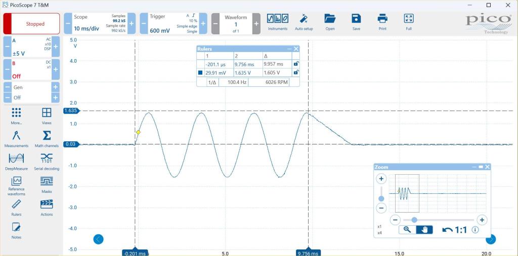 wherever the analogue value is at the time of the stop command the firmware ramps the voltage to vcc/2 over a period of 2.4mSec Edited 2023-04-01 03:22 by matherp |
||||
| Volhout Guru Joined: 05/03/2018 Location: NetherlandsPosts: 3585 |
Wauw, this is more then I had hoped for... But honestly, your explanation already is enough. I was just wondering why in 95% of the cases play stop worked perfect, and in 5% of the cases it stops at the top of a sinewave, unless it has something to do with the speed at which basic commands are processed. In 95% of the cases immediately, and in 5% there is a little delay (1/4 sinewave of 1kHz is 250us). I will try as soon as I get to it (today it is late)... time to leave the shed... Volhout Edited 2023-04-01 06:29 by Volhout PicomiteVGA PETSCII ROBOTS |
||||
| matherp Guru Joined: 11/12/2012 Location: United KingdomPosts: 8603 |
V5.07.07b32 / WEB V5.07.07b2 https://geoffg.net/Downloads/picomite/PicoMite_Beta.zip Fixes bug in F2 exit from editor introduced in b30 Improved implementation of PLAY STOP to avoid pops |
||||
| disco4now Guru Joined: 18/12/2014 Location: AustraliaPosts: 844 |
Beta32 also includes the fix so that LIBRARY DELETE does not also clear the current Program. Latest F4 Latest H7 |
||||
| thwill Guru Joined: 16/09/2019 Location: United KingdomPosts: 3863 |
Peter, does the new PWM audio *magic* add any perceivable delay (i.e. 2.4 mSec) to running programs or is it done incrementally / asynchronously, presumably using interrupts ? - I haven't noticed any delay but then again lazer-cycle does not really push the limits. Best wishes, Tom Edited 2023-04-01 08:44 by thwill Game*Mite, CMM2 Welcome Tape, Creaky old text adventures |
||||
| JanVolk Senior Member Joined: 28/01/2023 Location: NetherlandsPosts: 104 |
Hoi Peter, I noticed with the latest version PicoMite V5.07.07b32 that there are problems with I2C commands such as I2C write and I noticed that with list commands there are now 133 commands and edit is listed twice. Version V5.07.07b31 works fine. Jan |
||||
| matherp Guru Joined: 11/12/2012 Location: United KingdomPosts: 8603 |
What precisely. I tested with a BME280 and that worked fine yes thanks - fixed in next beta |
||||
| JanVolk Senior Member Joined: 28/01/2023 Location: NetherlandsPosts: 104 |
Peter, The problem was after the transfer with MMEdit4 to the PicoMite. The I2C Write commands are then changed and then an error after run. I tested it with a DHT20 temperature/RH sensor. (see section program DHT20 or AHT20 is an accurate and very stable I2C temp/RH sensor) Sorry, but unfortunately I can't reproduce it again, as luckily it's fine now with V5.07.07b32. I had the problem while investigating the reset and maybe something went wrong with the usb driver in windows? I am using a normal Raspberry Pi Pico with only the DHT20 sensor. If I reset the Pico more than 2 x with an interval of 3 seconds with a push button soldered directly to the PCB, the communication via the USB gets stuck and Terra Term can no longer detect the port. Only this usb com port no longer works and another board with a different com port still works. Placing a capacitor of 100nF and a pullup of 10K over the pushbutton doesn't help either. The only thing that helps is restarting the laptop. I work with Windows 10 (cannot be updated to Windows 11 due to the wrong processor) and when I look at Tera Term VT in the Setup it says Driver Date: 6-21-2006 and Driver Version: 10.0.19041.2130. I don't know if anyone on the forum has also had experience with this and a possible solution to this problem? I don't use the reset anymore and only in emergencies and when updating the firmware. dht20.bas ' Time$ = "hh:mm:ss" and Date$ = "dd-mm-yyyy" ' RTC SETTIME year, month, day, hour, min, sec te = 0 hu = 0 Do dht20_init dht20_read te,hu Print "DHT20: ", "Vocht:";Str$(hu,2,1);" %","Temp:";Str$(te,2,1);Chr$(176);"C", Print "Tijd:";Left$(Time$,5) Pause 60000 Loop End Sub dht20_init I2C Write &h38,0,1,&hbe Pause 100 End Sub Sub dht20_read(temp, hum) Local integer arr(6) I2C Write &h38,0,3,&hac,&h33,&h00 Pause 80 I2C READ &h38,0,6, arr() If (arr(0) And 128) Then Print "Gegevens niet beschikbaar, verhoog de wachttijd" Else hum = ((arr(1) << 12) + (arr(2) << 4) + (arr(3) >> 4)) / 10485.76 temp = (((arr(3) And &h0f) << 16) + (arr(4) << 8) + arr(5)) / 1048576 temp = temp * 200 - 50 EndIf End Sub > run DHT20: Vocht:57.9 % Temp:18.1°C Tijd:21:01 Jan |
||||
| matherp Guru Joined: 11/12/2012 Location: United KingdomPosts: 8603 |
I should have forced a complete reset with b32. The commands changed so a program stored in flash would be corrupted as the tokens were different. Any program loaded from disk (including flash disk) or via AUTOSAVE/MMEDit would be fine |
||||
| matherp Guru Joined: 11/12/2012 Location: United KingdomPosts: 8603 |
V5.07.07b33 / WEB V5.07.07b3 https://geoffg.net/Downloads/picomite/PicoMite_Beta.zip Support for MCP4822 DAC (8 pin version) for audio output 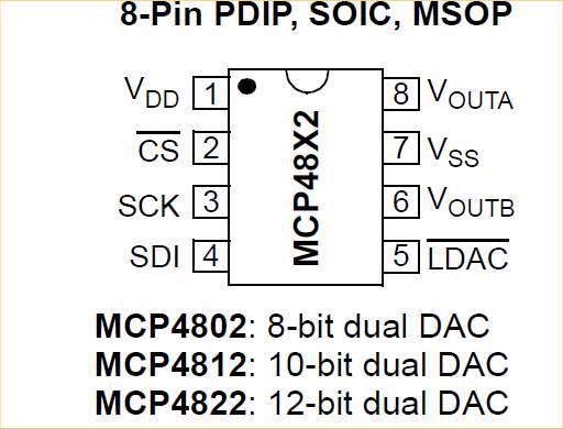 USE: OPTION AUDIO SPI CSpin, LDACpin, SCKpin, SDIpin to enable this. NB: SCKpin and SDIpin must be valid SPI TX and CLK pins as per the manual. The SPI channel is dedicated to the DAC and can't be shared. This mode will also use the PWM channel associated with the CLK pin chosen. e.g OPTION AUDIO SPI GP0, GP1, GP2, GP3 uses SPI and PWM 1 USE standard syntax for PWM AUDIO output Advantages of the DAC Available as a PDIP No complex filters needed Less noise on audio Internal 2.048V reference so voltage swing is between 0 and 2.048 volts Cheaper for production by JLC (less extended range components) Disadvantages 2 extra pins required one SPI channel and one PWM slice dedicated b33/b3 also changes the frequency used for PWM and SPI output for audio as follows CPU frequency 48-251MHz - 44100Hz CPU frequency 252-377MHz - 88200Hz CPU frequency 378MHz -132300Hz Picture shows PLAY TONE 3000,3000 with a CPU speed of 378MHz. This gives 132300/3000 = 44 samples per sine wav which you can just about pick up the individual levels on the scope. This is taken with the DAC on flying leads - hardly ideal - but still an excellent result 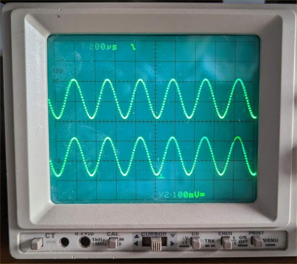 And here is a picture of PLAY TONE 13230,13230 The frequency is chosen to fit the DAC update rate so we get exactly 10 samples per waveforms 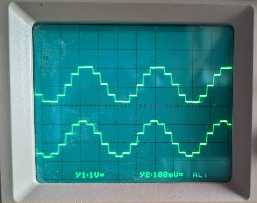 Final Pic PLAY TONE 13230\2,13230\2 Bottom trace has the DAC connected via a 100ohm resistor into a 100nF capacitor - all that is needed for a perfect trace 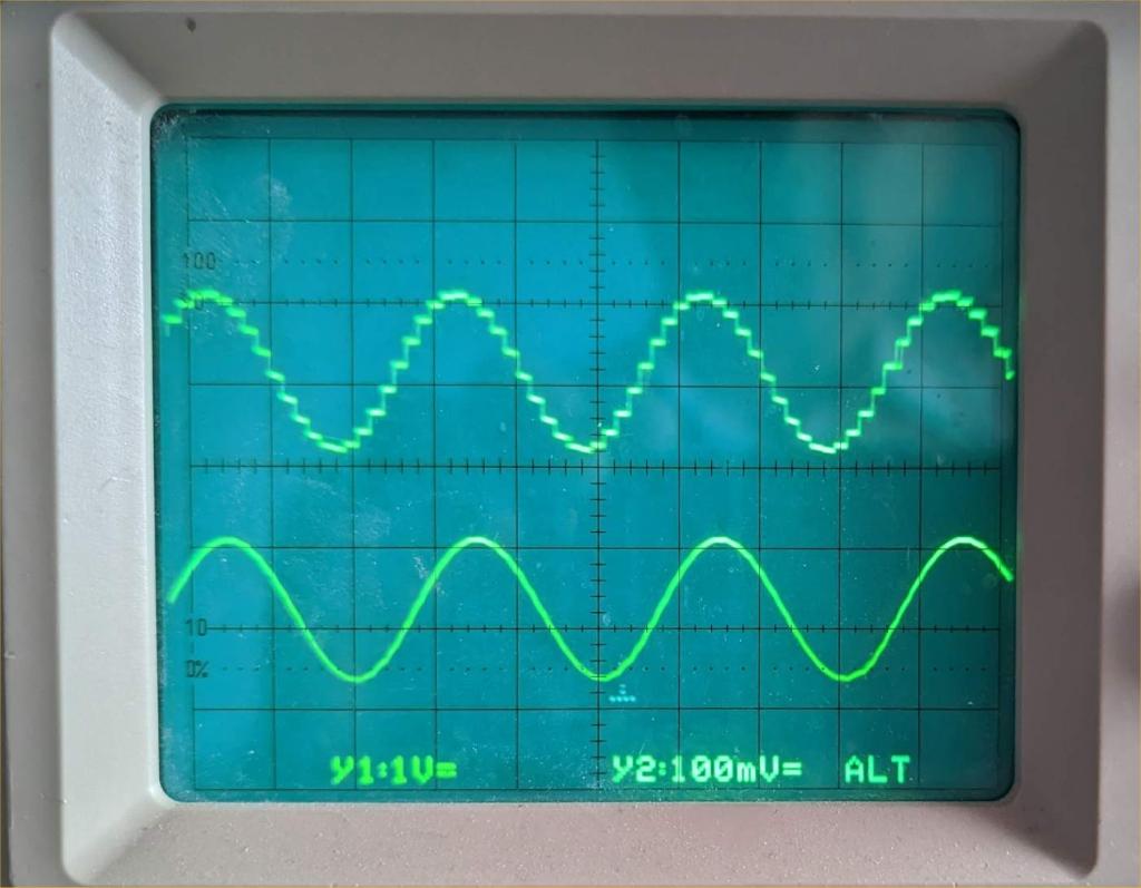 Edited 2023-04-02 22:16 by matherp |
||||
| Mixtel90 Guru Joined: 05/10/2019 Location: United KingdomPosts: 5768 |
Very nice! :) It costs more for the DAC than it does for the Pico though. lol Mick Zilog Inside! nascom.info for Nascom & Gemini Preliminary MMBasic docs & my PCB designs |
||||
