
|
|
Forum Index : Microcontroller and PC projects : Picomite(VGA) V5.07.07 betas - bug fixes + focus on PIO
| Author | Message | ||||
| matherp Guru Joined: 11/12/2012 Location: United KingdomPosts: 8578 |
1. Good  2. Files reserves a huge amount of RAM to sort the directory (up to 1000 files). Ram reserved for variables is maintained after Ctrl-C otherwise you would not be able to inspect them. Can't you use CLEAR to release the RAM? 3. I'll add a TILE RESET command to do this 4. Quite a bit of work, perhaps for marginal benefit, I use a camera  5 FONT 3 is 16x16 deliberately for this. |
||||
| Pluto Guru Joined: 09/06/2017 Location: FinlandPosts: 329 |
Combining Martin H's VGA idea and Volhout's PIO for Logic Analyzer: 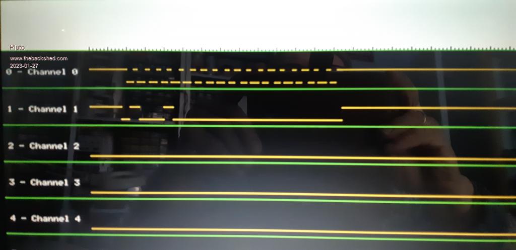 PIO 1.0 @6MHz PIO 1.1 @63MHz samples% = 1024 (much more than needed for the part visible on the screen; scrolling of data in mind) I had only a few GPIOs free on my PicoMiteVGA; using GP2 toGP7. Picture: I2C to address &h48 with data &h00 , 400kHz. (ADT7410 I2C Temperature Sensor). I2C communication is running on a second PicoMite connected to the temperature sensor. The PicoMiteVGA-Logic Analyser is just listening to the SDA and SCL lines. PIO 1.0 (collecting data) needs to be at min 6MHz in order to see the bits properly on the screen. PIO 1.1 (trigger) is superb. Thanks Volhout!  Next step would be to try to scroll sidevise on the screen to see what the temperature sensor sends back. Decoding of the I2C (and other protocols) would also be nice. Thanks to Peter, Volhout and Martin for your support and ideas! /Pluto |
||||
| matherp Guru Joined: 11/12/2012 Location: United KingdomPosts: 8578 |
Can I suggest a new thread for the logic analyser. It it probably of more general interest than a beta update thread |
||||
| Volhout Guru Joined: 05/03/2018 Location: NetherlandsPosts: 3510 |
@Peter, Question about the DMA. The DMA stores data in 64bit wide array. The DMA RX POINTER, is that a byte pointer pointing to the actual last written entry in the buffer, or is it the base address of the 64 bit value ? in other words, if I write 32 bits, does the pointer point to the 32 bits value, or to the 64bits register. I ask this becuase I see trigger jitter, that could be related to the pointer being the base of the 64bit, where as it could be the MSB 32 bit value written last. Regards, Volhout PicomiteVGA PETSCII ROBOTS |
||||
| matherp Guru Joined: 11/12/2012 Location: United KingdomPosts: 8578 |
The DMA RX POINTER is the address that the next DMA transaction will write to. It could be on a byte, short, or 32-bit word boundary depending on the setup of the DMA command. Remember that you are reading a fast changing value from Basic so it will always have some jitter depending on what you are doing. In your application it should be taken as a guide and then you need to look for the actual trigger in the data to centralise you plot |
||||
| Volhout Guru Joined: 05/03/2018 Location: NetherlandsPosts: 3510 |
I think I am reading after the PIO has finalized (is not writing any more data to the FIFO to the DMA) but it is a good suggestion to verify that that is actually the case !! Thanks ! PicomiteVGA PETSCII ROBOTS |
||||
| matherp Guru Joined: 11/12/2012 Location: United KingdomPosts: 8578 |
I would set an interrupt on the trigger pin and then read the pointer in the interrupt routine. Alternatively tight loop on the trigger pin changing state. That should get you somewhere close |
||||
| Volhout Guru Joined: 05/03/2018 Location: NetherlandsPosts: 3510 |
Hi Peter, The PIO engine will fill the DMA with pre-trigger data, until the moment it sees a trigger. Then it will store exactly "postrtigger%" samples more in the FIFO (DMA). Then it will stop, until ordered to restart. The MMBasic code checks the trigger in a basic loop, pauses a while (calculated from posttrigger% samples and the PIO frequency) + 10ms, then reads the position of the pointer in the DMA. That should have taken the last samples from the FIFO by then. From the DMA pointer, it subtracts "posttrigger%" and knows the original trigger point. Maybe I should make a timing diagram to explain... Sorry if it is confusing. Volhout PicomiteVGA PETSCII ROBOTS |
||||
| Volhout Guru Joined: 05/03/2018 Location: NetherlandsPosts: 3510 |
@Peter, I have one strange observation, and I am hesitant to try to duplicate it. Picomite VGA (I am running V50707b10, the last). The logic analyzer program uses a lot of RAM in arrays (80+ Kbyte). When I stop the program, I can see in "memory" that I do. As mentioned before, I can not run "files" since there is not enough memory. But I do NOT get a warning when I try to save the program to SD card after stopping the program. And I do this a lot. At every significant change, I save a new revision to SD card. This works fine, I can load the program back from SD card after a power cycle. So picomite can read the card. But as fate works, I cannot read the SD card in a linux PC, and not in a windows PC. Something is corrupted. The Linux PC will not read the file allocation table at all. Windows can read the file allocation table (it shows the file names and folders), but cannot open the file. Is this the card itself, or could it have been made corrupt ? A worried Volhout Edited 2023-01-30 22:18 by Volhout PicomiteVGA PETSCII ROBOTS |
||||
| JohnS Guru Joined: 18/11/2011 Location: United KingdomPosts: 3654 |
In case you didn't yet, maybe at least grab an image copy of the card (Linux dd or whatever). John |
||||
| Bleep Guru Joined: 09/01/2022 Location: United KingdomPosts: 411 |
Hi Peter or Volhout, I'm attempting to use the PIO DMA TX command to drive WS2812 LED strings. My code used to be:- Sub update() Local Integer x, y=0 ' Pack 4 sets of 3 bytes (RGB) into 3 32bit array elements ' So each 3 array element contains 4 led colour defs. ' RGBR,GBRG,BRGB For x=0 To 45 Step 3 fifo(x)=disp(y)<<8 Or disp(y+1)>>16 And &HFFFFFFFF:Inc y fifo(x+1)=(disp(y)<<16 Or disp(y+1)>>8)And &HFFFFFFFF:Inc y fifo(x+2)=(disp(y)<<24 Or disp(y+1))And &HFFFFFFFF:Inc y,2 Next ' Write out the LED colour defs to the PIO 8 at a time, buffer is 8 long. For x=0 To 40 Step 8 PIO WRITE 1,0,8,fifo(x),fifo(x+1),fifo(x+2),fifo(x+3),fifo(x+4),fifo(x+5),fifo(x+6),fifo(x+7) 'writes led colour Next PIO WRITE 1,0,1,0' Flush FiFo 'Memory Pack fifo(),pfifo(),48,32 'pfifo(24)=0' Flush FiFo 'PIO DMA TX 1,0,50,pfifo(),,, End Sub This produces the following logic sequence from the PIO 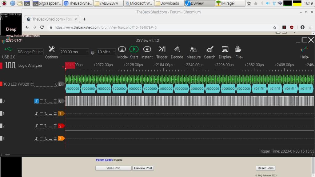 The first 12 LEDs are blank the the next 5 contain &H011F1F Which is correct. When I change my code to use the DMA TX :- Sub update() Local Integer x, y=0 ' Pack 4 sets of 3 bytes (RGB) into 3 32bit array elements ' So each 3 array element contains 4 led colour defs. ' RGBR,GBRG,BRGB For x=0 To 45 Step 3 fifo(x)=disp(y)<<8 Or disp(y+1)>>16 And &HFFFFFFFF:Inc y fifo(x+1)=(disp(y)<<16 Or disp(y+1)>>8)And &HFFFFFFFF:Inc y fifo(x+2)=(disp(y)<<24 Or disp(y+1))And &HFFFFFFFF:Inc y,2 Next ' Write out the LED colour defs to the PIO 8 at a time, buffer is 8 long. ' For x=0 To 40 Step 8 ' PIO WRITE 1,0,8,fifo(x),fifo(x+1),fifo(x+2),fifo(x+3),fifo(x+4),fifo(x+5),fifo(x+6),fifo(x+7) 'writes led colour ' Next ' PIO WRITE 1,0,1,0' Flush FiFo Memory Pack fifo(),pfifo(),48,32 pfifo(24)=0' Flush FiFo PIO DMA TX 1,0,50,pfifo(),,, End Sub I now get the logic sequence :- 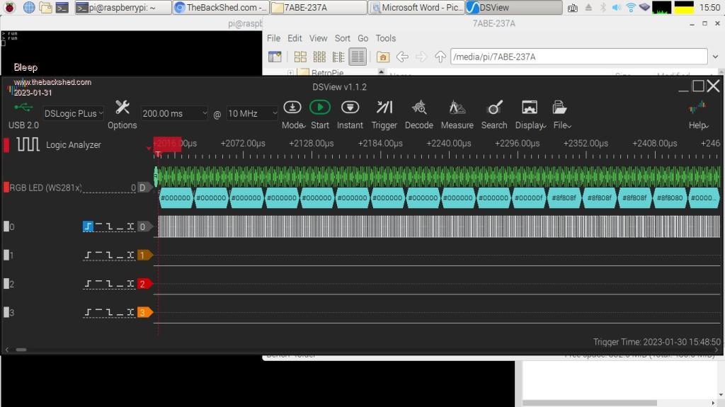 Here the first 10 LED are blank and then the data is scrambled. It looks like the data is rotated or shifted in some way? I've tried various other methods of packing the data, but so far, haven't managed to get the DMA TX to drive the LEDs correctly. Any ideas/suggestions. Regards, Kevin. PS, this is using the latest VGA. PicoMiteVGA MMBasic Version 5.07.07b10 OPTION SYSTEM I2C GP22,GP15 OPTION COLOURCODE ON OPTION KEYBOARD UK OPTION CPUSPEED (KHz) 378000 OPTION DEFAULT MODE 2 OPTION DISPLAY 80, 160 OPTION SDCARD GP5, GP2, GP3, GP4 OPTION AUDIO GP6,GP7, ON PWM CHANNEL 3 OPTION RTC AUTO ENABLE OPTION F6 Edit 1 OPTION F7 Edit 2 OPTION DEFAULT FONT 8, 1 Edited 2023-01-31 02:39 by Bleep |
||||
| Volhout Guru Joined: 05/03/2018 Location: NetherlandsPosts: 3510 |
Hi Bleep, I do not see your complete program, that would definitely help. I am most interested in the PIO program, and especially the FIFO configuration. From the "working" part I understand you are chaining FIFO's. It would definitely help to do without chained fifo's (just to make sure thatit is causing a problem). The DMA is fast enough. I have checked the "PACK" with my own data (not RGB) but the pack seems to work Okay. The problem I see is in the OPTION BASE Since you use X=0 as lowest index in the fifo() array, I expect you use option base 0 (the default). The fifo array should be integer, as is the pfifo array. In my code I make sure they are integer because I add the % to the name. Option base 0 DIM fifo%(47) 'contains the 48 32 bit values The pfifo%() array contains the 64 bit DMA values (2 32 bit values per cell) This array MUST be integer, because 64 bit floats cannot be stacked (2 per cell). DIM pfifo%(23) 'contains 24 64 bit values Now the arrays match, and the pack will line up. But how can you (in your code) flush pfifo with pfifo%(24)=0 This should give an error. So I expect you have not dimension-ed the arrays correct. In which case the DMA may become confused. And if you are sending 50 values that do not line up with multiples of 24bits for the WS2812's, you can expect strange behaviour. Please provide the complete code. Maybe there is more I can find. Edited 2023-01-31 06:36 by Volhout PicomiteVGA PETSCII ROBOTS |
||||
| Bleep Guru Joined: 09/01/2022 Location: United KingdomPosts: 411 |
Hi Volhout, Sorry, yes all arrays are Integer, base 0, I always declare every variable and its type. All that pfifo(24)=0 is doing is putting 0 in the last array element, so that when the data is sent, extra 0's are sent at the end of the transmission sequence. There are 64 leds, packed as 4 RGB leds, in each 3x32 bit array element, so fifo() is 48 in size. This should then PACK as 24, 64 bit words in pfifo() 0 to 23, pfifo(24) I manually set to 0. I will try not chaining the fifos, but I would hope that doesn't make any difference. I'll attach the whole program tomorrow, it's quite large. Regards Kevin. Edited 2023-01-31 07:07 by Bleep |
||||
| Bleep Guru Joined: 09/01/2022 Location: United KingdomPosts: 411 |
Hi Volhout, Have tried without joining the fifo, no difference. Here is the complete code. Note the only changes made were as listed above in Sub update(). Both versions are in this code, one set commented out. wc.bas.zip Hope you can spot what I'm doing wrong. Regards, Kevin. Edited 2023-01-31 08:51 by Bleep |
||||
| matherp Guru Joined: 11/12/2012 Location: United KingdomPosts: 8578 |
It would be much better to start with a integer array of 64 elements pack it and then DMA it to the PIO. Once that is working then the rest is just Basic . Are you shifting in 24-bits per time or 32? 32 - would be by far the easiest to interface to. i.e. send each pixel as a 32-bit value and in the pio pull in the word and shift out 24 bits with the relevant timing then pull in the next. DMA will feed as fast as you need. |
||||
| Volhout Guru Joined: 05/03/2018 Location: NetherlandsPosts: 3510 |
This is a good suggestion, but since Bleep is using autopull, it will be a complete re-write of the WS2812 PIO program. Kevin, there is a requirement if you use the DMA (I have no experience with TX DMA< but this is a requirement for RX DMA, so I think it is needed for TX too). Every time you start the DMA, the DMA will start the PIO. But the DMA will not configure the PIO. When PIO is stopped it will be at a certain instruction. DMA only starts it, it does not start at address 0. So before starting DMA do a PIO STOP 1,0 PIO init machine 1,0,fr0,p0,e0,f0,0 That may solve the issue. Edited 2023-01-31 19:35 by Volhout PicomiteVGA PETSCII ROBOTS |
||||
| Volhout Guru Joined: 05/03/2018 Location: NetherlandsPosts: 3510 |
@peter When I define a packed array, to be used for DMA, with option base 0, the index in the array can vary from 0 to (size-1). DIM packed%(2047) will have index 0...2047 When I use this array for the DMA, and the DMA times out (&h7fffffff samples): With PIO filling DMA at 21.5MHz, the time out happens after 102 seconds. PIO DMA RX 1,0,&h7FFFFFFF,packed%(),ReadyInt,32,samples% The pointer after timeout can be calculated from: varindex%=(Pio(DMA RX POINTER)-Peek(VARADDR packed%()))/8 The varindex% has a value of 2048. It is not in the range of 0...2047. This only happens when the counter overruns at &h7fffffff, I have not seen it happen in normal use. But that can be incidental. I can work around this artefact, but maybe it is something that needs fixing. Is there a possibility to use a 64bit variable for the maximum number of samples, or change the value to an unsigned value ? Volhout Edited 2023-01-31 20:04 by Volhout PicomiteVGA PETSCII ROBOTS |
||||
| matherp Guru Joined: 11/12/2012 Location: United KingdomPosts: 8578 |
No the silicon only allows 32-bits. You can use &HFFFFFFFF. The report from the RXC pointer is just read from the register so is presumably what the silicon does - inc then stop |
||||
| Bleep Guru Joined: 09/01/2022 Location: United KingdomPosts: 411 |
Hi Volhout & Peter, Volhout has hit the nail on the head :-) it was that the DMA was starting the PIO at the wrong point, re-initialising it for each data burst is now producing the correct bit sequence. I do also like Peters suggestion of DMAing the data as 24bits (in a 32bit word) as I already create that and then discarding the extra 8 bits for each LED, it would save all the shifting and masking to get the 24bits sequentially packed into 32bit words, maybe my next challenge, but it could be tricky, to still keep the timing of the High/Low transitions within spec. (Anon. I just had a brain wave, can't you define how many bits are shifted out, before the autopull happens, I currently set this to 32, but maybe if I set it to 24???) Almost anything is possible. :-) Thank you both for some great suggestions. :-) Regards, Kevin. |
||||
| Bleep Guru Joined: 09/01/2022 Location: United KingdomPosts: 411 |
Hi Peter Volhout, That's worked :-) I have had to move the RGB data up by 8 bits, in my display array, which I can do while filling it, but then all I have to do is PACK it and set the PIO to auto pull after 24 bits so the last 8 bits are discarded. So I've, or rather Peter, has managed to get rid of a whole load of byte shuffling, very pleasing. :-) And yes it's going significantly faster using the DMA. :-) So fast I had a crash, because the DMA had not finished sending, by the time the Basic was ready to send the next array of screen update! Regards, Kevin. |
||||
