
|
|
Forum Index : Microcontroller and PC projects : Hoping for some MPASM Assembler help.
| Author | Message | ||||
| JimDrew Newbie Joined: 07/10/2020 Location: United StatesPosts: 39 |
OK, so good news... your ISR code works perfectly for traversing up and down your table. FSR0 is the correct result every time the interrupt is fired. So, this is not your problem. I was not able to get the simulator to work to trigger the ISR though. I had to manually go into ISR. The PWM5 output IS working correctly, and the PWM5INTF flag is being set but the PWM5IF flag in PIR6 is not being set. I am not sure if this is a simulator thing or not. I have NO experience with this part and its DAC. It looks like your DAC setup is correct though. I am a bit surprised that you have to use the DACLD to force the sample into the buffer, but hey, Microchip has changed this a few times over the years. The first thing I thought was that you didn't notice that the output from the DAC is extremely low current which requires a unity gain buffer. I typically use a MCP601 for that, and then I saw in your setup that you are pointing the DAC outputs internally to the built-in OPAMPs. That's pretty nifty if these will handle sufficient current for your application. So... what is wrong? I am 100% convinced that your table is working, but I am not sure about the interrupt setup. The PWM itself is definitely working as I can see it toggling the output in the simulator. I would recommend toggling a spare pin from within the interrupt (like at the start of your ISR) and looking at that pin to see if it really toggles. This will tell you with 100% certainty that the interrupt is working all of the time, and just not the very first time it is enabled (which I have seen before when something is not setup quite right). Microchip has had a bad habit of requiring an EXACT order of operations for certain peripherals to work. Typically you have to bit-set everything, with the enable done last. I also don't know if the setup for the DACs and OPAMPs is correct. I would recommend that you enable the DAC1OUT1 and DAC2OUT1 outputs to the pins, which will appear on RA2 and RA5, respectively. You didn't provide a pin usage map, but I think these are free. You can put a scope on these while it is running to see if the outputs change here vs. where the OPAMPs outputs are assigned (RA1 and RB1). To do that just enable the pin outputs: bsf DAC1CON0,OE1 bsf DAC2CON0,OE1 This could simply be a setup issue (order of operations) for the DAC or OPAMP setup. I don't think the interrupt setup is wrong... it's what I would do, but you need to actually do something within the interrupt (toggle a pin) to verify it is working... just having the PWM5 output sent to a pin via PPS is only going to show you that the PWM is working (and it is for sure). That's my 2 cents. I am going to see if I can find a design reference for this family that shows setting up the DAC and OPAMP. Jim |
||||
| JimDrew Newbie Joined: 07/10/2020 Location: United StatesPosts: 39 |
Attached is the project. I moved your ISR code into the main program (at 0x0004) because ever since MPLAB-X was released the debugger won't move between individual include files as you walk through code (in the simulator or a hardware level debugger). The PC always changes and you can watch the code run as instructions in the PROGRAM MEMORY window, but any code location outside of the main code page (0x0000 - where the code starts) won't show any of the labels/changes unless you make a full cross-reference for every sub-routine on every include you use. I prefer the old method that MPLAB8 does where it just follows the PC across multiple different includes, opening them if necessary. So, your ISR is in the main page and can be walked through easily. Also, don't forget to change the TRISx for any pins you setup as outputs for toggling. In fact, you might want to check to see what the TRIS needs to be set to for the output of the DACs & OPAMPs too. I know some peripherals that output should be TRIS'd to inputs, but I am not sure what is required for the DAC and OPAMP outputs. DAC_Code.zip Edited 2023-02-03 19:25 by JimDrew |
||||
| JimDrew Newbie Joined: 07/10/2020 Location: United StatesPosts: 39 |
So, after a few hours of looking around I found that every example from Microchip, and even the MCC code creator always enables the DAC as the very first thing it does, followed by setting up any registers. You have this: movlb bank_1 ; ( Bank 1.) movlw b'10001000' ; Enable FVR_2 Buffer 2 o/p for DAC's, Gain x2. movwf FVRCON movlb bank_11 ; ( Bank 11.) movlw b'01001000' ; DAC 1 is Disabled, LEFT justified, no external O/p's movwf DAC1CON0 ; +ve source is FVR_2, -ve source is AVss. ( Vss.) movlw b'01001000' ; DAC 2 is Disabled, LEFT justified, no external O/p's movwf DAC2CON0 ; +ve source is FVR_2, -ve source is AVss. ( Vss.) ..and then later in the setup code you have this: movlb bank_11 ; ( Bank 11.) movwf DAC1REFH ; and put into DAC 1. ( LEFT justified.) clrf DAC1REFL ; ( DAC1REFL<7:6> 2 bits not used.) movwf DAC2REFH ; Also put into DAC 2. ( LEFT justified.) clrf DAC2REFL ; ( DAC2REFL<7:6> 2 bits not used.) bsf DACLD,DAC1LD ; Output the sample, bsf DAC1CON0,DAC1EN ; and enable DAC 1 output. bsf DACLD,DAC2LD ; Output the sample, bsf DAC2CON0,DAC2EN ; and enable DAC 2 output. Based on the examples I have seen (and past experience with certain peripherals that need to be "ON" before they will accept any changes), you might try enabling the DAC first, ie: movlw b'11001000' ; DAC 1 is Enabled, LEFT justified, no external O/p's movwf DAC1CON0 ; +ve source is FVR_2, -ve source is AVss. ( Vss.) movlw b'11001000' ; DAC 2 is Enabled, LEFT justified, no external O/p's movwf DAC2CON0 ; +ve source is FVR_2, -ve source is AVss. ( Vss.) ... then get rid of the two lines that were enabling the DACs. One other small reminder that I see everywhere - you can't use the DAC *while* the programmer (or debugger) is plugged in or you won't get anything out of it! |
||||
| Bowden_P Senior Member Joined: 20/03/2019 Location: United KingdomPosts: 162 |
Hi Jim, Many thanks for all the time you have put in on this enigma ! I can confirm a few of your points mentioned above :- I have toggled an o/p pin in the ISR to check that it is being called - was working as expected. ( The "flags,isr_toggle_f" currently commented in the Equates file was used for control.) The DACs are succesfully buffered by the on-chip op.amps. OPA1 and OPA2, outputting on RA1 and RB1. They commandeer their pins when enabled, and are a really useful feature ! The DAC's are double-buffered due to needing 2 bytes to program, so setting DACxLD controls a simultaneous transfer, and is then cleared by the hardware. Microchip datasheets are frequently wooly about the order of setting up a peripheral. Often all you get is an explanation of the registers, so my adopted approach is to set all registers as required, then hit the Enable bit ! (On some they do say to disable the peripheral before making changes, perhaps due to trying to avoid a spurious interrupt or output.) In the DAC_Code_ISR.inc file are 2 other options for the ISR (commented). One uses the complementary "MOVIW,--/++FSR0" instruction - didn't work either. The other works with program memory data recovery for the DAC's - which worked immediately. I found earlier that if the MOVIW was aided by manually incrementing /decrementing FSR0 prior, then the expected waveform was output - almostly correctly. Not much point doing that with MOVIW !! This is how I have come to conclude that the chip execution of MOVIW is faulted. I have tried usig the simulator in my MPLABX v3.65, and can confirm I also get no interrupt activity, just endless Main Loop looping - so apparently no surprise there now. I'll look at your .zip code and see if there is any change here. Thanks again for all your work, With best regards, Paul. Nothing so constant as change. |
||||
| Bowden_P Senior Member Joined: 20/03/2019 Location: United KingdomPosts: 162 |
Hi Jim, Just to confirm I get no interrupt activity in my v3.65 simulator with the ISR code in the main .asm at org &x0004. With best regards, Paul. p.s. Earlier I added an active 2-pole Butterworth filter to the DAC 2 output using the last on-chip op. amp - OPA3 - and out popped a rather good sine wave. Very pleasing ! Edited 2023-02-04 06:48 by Bowden_P Nothing so constant as change. |
||||
| JimDrew Newbie Joined: 07/10/2020 Location: United StatesPosts: 39 |
Yeah, this must be an issue with the simulator then. I noticed that there are several "yellow blocks" for the supported features, so this could be one of those. Your ISR code for generating the value to put into the DACs is working 100%, so that is absolutely not the issue. You can just move the PC to "isr_pwm5_start" in your ISR and walk through the code until the RETFIE, then move the PC back again and repeat over and over. You will see that the value being fetched from table is always correct, moving up and down the table just as you intended. So, if the interrupt is really firing then I think this has to be an issue of the data being put into the DACs is not being updated - likely from not enabling the DAC first before doing any setup of the registers. You set several things after the fact that directly affect the operation of the DAC. When the MCC code creator enables something first before changing the associated registers then that would be a good clue. The OPAMP initialization with MMC code creator enables the OPAMP module very last thing. So, if you put a pin toggle in the ISR and it is for sure firing every PWM5 timeout then the issue has to be with the DAC storage, since you seem to be able to get something out of the OPAMP output pin assignment. As I stated before, I have seen some peripherals that "sort of" work when not setup correctly. I don't recall what it was, but I ran into this same type of problem where a peripheral had to be enabled first, then associated registers setup or it would not function correctly, much like what you are experiencing now. Also, make sure that your programmer is unplugged from the ICSP if you are using that for programming. The ICSP (dat or clk) is connected to the DAC apparerntly, and you get nothing or random data from the DACs when the programmer is connected. Edited 2023-02-04 07:48 by JimDrew |
||||
| Bowden_P Senior Member Joined: 20/03/2019 Location: United KingdomPosts: 162 |
Hi Jim, Thanks for all your confirmations about my code - very reassuring ! As to programming - I put the device into a homemade jig with a ZIF socket complete with its own power supply, and have a PICKit 3 connected to do that. The device is then transferred to a breadboard to run the code. MCLR, ICSPCLK and ICSPDAT are not connected there, but MCLR is pulled up. I think that as both DAC's output the expected data reliably using the Program memory technique, the setup sequence is OK. I have used EEPROM in the past on such chips as PIC16F877A, where the use requires a very specific sequence to get success, but if there was a rigid sequence to follow for the DAC's then Microchip should really have nailed it down in the datasheet ! Hey-ho, wishful thinking I guess. I have found their datasheets have some omissions or contradictions, and you end up reading between the lines sometimes. This device is no exception. I guess it will happen somewhere in the 578 pages it runs to. Blindly copy-and-paste-ing is often the criminal here ! With best regards, Paul. Edited 2023-02-04 09:24 by Bowden_P Nothing so constant as change. |
||||
| JimDrew Newbie Joined: 07/10/2020 Location: United StatesPosts: 39 |
Typically the examples in the datasheets work. It's pretty rare there are mistakes, but I have reported a few myself. The silicon guys hated me for a few years because I was always finding silicon bugs because I write only in assembly code. You will find many erratas for the PIC24F parts where delays are required after writing to a register before reading the result - I found many of those cases (which never occur when writing in C due to the inherit delays). If the "program memory technique" seems to work then I would guess this would have to be some sort of timing issue of writing to the DAC registers. Your ISR code works, and the values being poked into the DAC are from the table so there are no issues associated with that, and walking through the code easily proves that. I will go look at your program memory technique version. Maybe its something as simple as needing a NOP after writing to the DACs before forcing the load with DACLD? I have seen stranger things. The datasheet itself does not state anything about the setting up the DAC registers, but every example I have seen enables the DAC first and then sets up the attributes for the DAC. The fact that the Microchip code creator also does this leads me to believe that this is not optional. That is something you should always follow whne in doubt of the order of instructions to follow. I would recommend that you try enabling the DAC first instead of disabling during setup and enabling it at the end. MCC only works with v5.45 and later of MPLAB-X, but you can look at some example code for the PIC16F1709 which has a similar DAC setup. https://microchipdeveloper.com/mcu1101:project-11 I ordered a PIC16F1776 today for testing myself because it would be good for me to know if there are any quirks with this for any future use of this (or similar family) part. So, I will know exactly what this issue is as soon as that arrives. I am actually interested in the OPAMP output as I have a project that could be simplified by eliminating the external dual OPAMP. I am still puzzles about why the simulator does not trigger the interrupt. If you manually set the PWM5IF bit the interrupt immediately triggers. This indicates that the basic interrupts are setup correctly. For some reason when the PWM5 timer matches the interrupt bit is not occurring. Edited 2023-02-04 15:46 by JimDrew |
||||
| JimDrew Newbie Joined: 07/10/2020 Location: United StatesPosts: 39 |
I looked at your "program memory technique" vs the "moviw" version. There is one difference between the two that could be the reason for what you are seeing. You noted this: ; Clearing the individual "PWM5INTF,PRIF" interrupt flag also clears the Group "PIR6,PWM5IF" flag apparently, ; so no need to clear that too. So, your "program memory technique" version is missing the line of code that clears the main interrupt flag for PWM5IF, but this line *is* in the "moviw" version: bcf PIR6,PWM5IF ; and the PWM5 group PIR6 flag. (Probably redundant.) I guess you could omit this line from the "moviw" version and see if it magically works. Ironically, the PWM5IF is what is NOT triggering under the simulator. Where exactly did you put the code to toggle a pin when an interrupt fires? I see toggling RC2 to show the main loop is working, but there is no type of DEBUG data to toggle a pin from within the ISR itself. The TRIS registers are also not set to outputs for anything except for RC2 (main loop toggle) and RC3 (PPS re-direction for PWM5 output). Edited 2023-02-04 16:24 by JimDrew |
||||
| Bowden_P Senior Member Joined: 20/03/2019 Location: United KingdomPosts: 162 |
Hi Jim, Thanks for your replies. I would be interested in the datecode and version number you have on your '1776's when they arrive. Mine were bought from RS here in the UK about last July, and have a datecode 1539PWO, version A1, 2001h. ( Consistent with my Datasheet DS40001810B, and Errata DS80000690A.) Recently checked, these are still current. Interrupt flags - hmmm. There is no mention of the grouped PWM interrupt register/bit "PIR6,PWM5IF2" in the 16-bit PWM Section 26, or what it does. A case of "reading between the lines". This PWM can produce up to 4 interrupts depending on the mode selected, and I assume that these are OR-gated into the PIR6 register bit. Again no data on that. I did find that as I only have the Period interrupt enabled (end of the "DAC_Code_Ini.inc" file) :- MOVLW b'00000001' MOVWF PWM5INTE I found that didn't need to clear the PIR6 bit as well in the ISR - it cleared itself, as I got no repedative ISR re-entry when checked experimentally. If you were using more of the features of this quite complex PWM, then flag sorting in the ISR would be aided via using PIR6, but not for me conveniently. BTW - although I don't use the Duty Cycle feature or interrupt, I needed to set it to something sensible for the Period interrupt to work ! ( Originally cleared to 0%, now set to 50%.) You mention putting a NOP between writing to the DACs before forcing the load with DACLD. There is a slight pause here by the instruction "MOVLW b'00000001'". Much of my "DEBUG" code has been removed from the .zip'd files - when I am debugging usually I just comment abandoned debug instructions, but this eventially results in a horrible mess as you can imagine - I would hate to post those ! The files posted here have been "sanitised" somewhat. Attached .zip is the RC2 toggling addition to the ISR, and where I put it. ISR RC2 Toggling code.zip With best regards, Paul. Nothing so constant as change. |
||||
| JimDrew Newbie Joined: 07/10/2020 Location: United StatesPosts: 39 |
Yeah, the info on the interrupt is a bit vague, but I think it is much like other peripherals with multiple components - there is a main interrupt flag and sub-flags for the various attributes. I have never seen anything though that had a self clearing interrupt flag. In the simulator the PWM5IF is not firing. When I do that manually, the ISR is entered and everything appears to work (the proper value is put into the DAC from the table, direction flag changes as needed, etc.) Commenting out the line where you clear the PWM5IF flag results in the interrupt immediately firing again after the ISR exits with RETFIE (which I would expect since the flag is not cleared). So, the simulator doesn't clear this automatically - but the simulator never actually fires in the first place. When the PIC16F1776 arrives I will let you know the date code. I will use the ICD4 to walk through this at a hardware level. The DAC output won't work, but the ISR and such will work and I will be able to figure this whole thing out by looking inside of the chip at the registers. Things like this are why I love the MPLAB ICE (and now ICD4 that has taken its place). |
||||
| Bowden_P Senior Member Joined: 20/03/2019 Location: United KingdomPosts: 162 |
Hi Jim, I have just written a short program that exercises MOVIW FSR--/++ without any interrupts, subroutines, and minimal initialisation. Straight line code if you will. It runs from the internal oscillator at 32MHz, so needs no external components at all. It ran the same at 4MHz and 16MHz too. MOVIW Test.zip Enigmatically, it behaves to spec. The code reads a toggling table of just 4 o/p states in a table in GPR Bank 0, running up and down the table manually. There are 3 o/ps :- RA3 - 'scope trigger, RB3 - a straight switched output, RC3 - a copy of RB3, but using MOVIW recovered data from Bank 0. Expected waveforms are shown in the file. With best regards, Paul. Nothing so constant as change. |
||||
| JimDrew Newbie Joined: 07/10/2020 Location: United StatesPosts: 39 |
Like I said before, your original ISR code using FSR0++ and FSR0-- works fine. I believe the issue you are having with that code is a setup problem with the DAC (or the interrupt is really not firing after the 1st time)... there is some oddity with PWM5IF. Your new example code works perfectly and generates the expected waveforms as you can see with the Logic Analyzer (built into MPLAB-X). 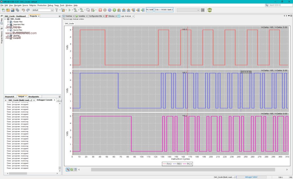 Edited 2023-02-06 17:36 by JimDrew |
||||
| Bowden_P Senior Member Joined: 20/03/2019 Location: United KingdomPosts: 162 |
Hi Jim, Oh dear-oh dear !! A salutory lesson indeed in understanding the datasheet.... It all comes down to automatic context saving/restoring and those "shadow" registers in Bank 31, and what they do. On branching to the ISR the FSR's are saved in the shadow registers, and restored on exiting. My program incremented or decremented FSR0 in the ISR for the next time the ISR was called. Problem was this inc./dec. was nulled on exit by the automatic restoration from the shadow register - hence next interrupt call the FSR0 hadn't changed, so the value extracted from the sample table was always the same - no output waveform. It's all very logical of course. The cure is to increment or decrement the FSR0 shadow register before leaving the ISR. Thanks to all contributors to this thread - and I hope my stupid miss-understanding will be of some benefit. At least Jim you will have some on-chip op. amps to play with. Many thanks for all your time and effort too. With best regards, Paul. Edited 2023-02-07 12:12 by Bowden_P Nothing so constant as change. |
||||
| JimDrew Newbie Joined: 07/10/2020 Location: United StatesPosts: 39 |
Well, that's new! The FSR's were never saved in other families that I have worked with. You always had to save/restore these if you used them. Typically, I would dedicate FSR0 for use with interrupts only so they would not need to be saved - just prevent the issue here. If the simulator's interrupt handling would have worked, I would have seen this instantly. Glad you figured this out. Can you tell me what you did to make the 3rd op-amp act as a LPF? Edited 2023-02-08 07:00 by JimDrew |
||||
| Bowden_P Senior Member Joined: 20/03/2019 Location: United KingdomPosts: 162 |
Hi Jim, Access is provided to connect all 3 terminals of an op. amp. to device pins. See section 29, page 368 in the spec. This figure has a number of errors - I've got 3 sticky note corrections for this page alone ! For OPA3 :- Contrary to Figure 29.1 showing OPA3 having 2 possible external pins each for the +/- inputs, there is only 1 each allocated in the Pin Allocation Table 3, page 6. +ve input can only go to RC5, pin 16, OPA3IN0+. -ve input can only go to RC7, pin 18, OPA3IN0-. Output goes to RC6, pin 17, OPA3OUT. Register OPA3PCHS<3:0> selects the +ve i/p source, set to OPA3PCHS<0000>. Register OPA3NCHS<3:0> selects the -ve i/p source, set to OPA3NCHS<0000>. When enabled via the OPA3CON<7> bit = 1, the module commandeers the o/p pin OPA3OUT. No pins are declared as Analog in the ANSEL registers - not sure if that is correct. The OPA3CON register is set to b'1000000',h'80' - Enable only. I can't make a circuit diagram other than this effort ! || |----------||----------------------| | || | | 10nF | | | \ | | | \ | 7.5K | 7.5k 16 | \ | I/p o--\/\/\/--o--\/\/\/--o------| + \ | | | \ 17 | DAC samples 8-248 | | OPA3 |-----o---o | | ==== / | 10nF ----- 18 | / | ----- |-| - / | | | | / | | | | / | | | | | | 22K | | o--------\/\/\/----| | | | \ | / | \ 39K | / | \ | / | | | | Gnd. o---------------------o----o------------------------o This Butterworth filter has an Fcuttof of about 2.2KHz, used to filter the DAC output of 500Hz. Fundamental of the DAC1 o/p samples is 10KHz. ( 20 x 500Hz.) The Fixed Voltage Reference O/p 2 used for the DAC is set to x2, = 2.048V o/p, with the 11 sample data going from lowest d'008' to d'248' highest. These values are only put into DAC1REFH<7:0>, DAC1REFL<7:6> is not addressed, effectively rendering the 10-bit DAC as 8-bit. These 11 samples give a sine wave when L.P. filtered :- Degrees : -90 -72 -54 -36 -18 0 +18 +36 +54 +72 +90 DAC 1 : 8 14 31 57 91 128 165 199 225 242 248 My apologies for the data error in the.ini file in the last full program .zip. Here is the correct - and working - code. The device oscillator will require a 8MHz crystal on OSC1/OSC2, RA6/RA7, pins 10 and 9. The device Vdd = 3.3V. DAC_Code_2.zip With best regards, Paul. Edited 2023-02-08 10:47 by Bowden_P Nothing so constant as change. |
||||
| JimDrew Newbie Joined: 07/10/2020 Location: United StatesPosts: 39 |
Hey, thanks for this info! I was curious how you were able to wire this as a traditional op-amp. I guess it is just like having one externally. Is the internal oscillator not stable enough for this? |
||||
| Bowden_P Senior Member Joined: 20/03/2019 Location: United KingdomPosts: 162 |
Hi Jim, Yes, it's really handy to be able to use these on-chip components independently if required. The internal oscillator would be fine for most uses at +/-2% accuracy. I have used a crystal just to improve on this - to about 0.003%. ( Its only an inexpensive crystal at 30 p.p.m.) With best regards, Paul. Nothing so constant as change. |
||||
| The Back Shed's forum code is written, and hosted, in Australia. | © JAQ Software 2025 |
