
|
|
Forum Index : Microcontroller and PC projects : Picomite VGA Logic analyzer
| Author | Message | ||||
| Volhout Guru Joined: 05/03/2018 Location: NetherlandsPosts: 3555 |
known bug solved. minor change. On my way to version 0.14.... Volhout PicomiteVGA PETSCII ROBOTS |
||||
| Volhout Guru Joined: 05/03/2018 Location: NetherlandsPosts: 3555 |
All folks, this is logic analyzer V0.14 This is what I would call alpha 1. When there are volunteers, try to put it to the test. There will be a user manual later, showing the technique behind it. Since I hear some complaints about picomites that do not perform well at 252 MHz, run this version with OPTION CPUSPEED 126000 (the default picomite VGA speed. The sampler runs at 126MHz and samples data up to 42MSps. The trigger engine also runs at 126MHz, but can require up to 100ns pulses, depending on the complexity of the trigger requirements. The logic analyzer uses GP22 as an internal signal. pins GP0...GP5 can be connected to circuits under test (3.3V logic) and like a 6 channel oscilloscope you can observe the signals. Pressing r will put the LA in run mode (default) and it will show the signals at the 6 pins. pressing s will perform a single capture, and stop. Each s will restart a new capture. The LA captures 4096 samples at various speeds. The display will show 128 of these samples at a time. You can zoom in and out with the UP and DOWN arrow keys. Above the 6 waveforms there is an indicator bar showing what part of the 4096 samples you are viewing. You can move your viewing window through the 4096 samples using the left and right arrow keys. Triggering is an important feature of a logic analyzer. It can help you to select a specific part of a waveform. In example I2C. When you connect an I2C signal to GP0 (SCL) and GP1 (SDA) you can view these signals. If you want to capture the beginning of a I2C message you should trigger on the I2C bus START condition. An I2C START condition happens when the SCL clock signal is high, and the SDA data signal changes from high to low (falling edge). This can be set up when Channel 0 (GP0) is "1". This can be set by pressing the "0" key on the keyboard, until the "1' is indicated for channel 0 Channel 1 (GP1) is going from 1 to 0. This can be set up by pressing the "1" key on the keyboard until the "\" symbol is highlighed for channel 1. Since the I2C bus is fast, it may be desired to increase the capture speed of the logic analyzer to 1 or 2 MS. This can be achieved by pressing the "+" and "-" keys until the speed indicator indicates 1MS. Now you should see each new I2C message (the start of it). If you want to study the message, press "s" to stop the sampler, and you can inspect the waveform by using the arrow keys. When pressing the number keys, you will also be able to change the channel name. This should not present much of a problem to edit. The name can be 9 characters maximum. I hope this meager introduction will get you going. Take a look at the signal from a NES controller (not I2C, but you can also trigger on it), the real time clock, the 44kHz PWM on the audio pins GP6 or GP7, or a serial port. Happy playing .... '+----------------------------------------------------+ '| logic analyzer framework research program | '| | '| Volhout 31-1-2023 | '+----------------------------------------------------+ 'samples GP0...GP5 with triggering on GP22 'uses PIO and ring buffer under DMA. 'requires V50707b10 or newer '---------------------- version control ---------------- ' LA_3 uses DMA after manual trigger, serial output ' LA_4 uses DMA and ring buffer, serial output ' LA_5 testbed to debug DMA ' LA_6 restructure (this version) tbd PIO is ready ' LA_7 unroll circular buffer to linear array ' LA_8 triggering works ' LA_9 basic VGA display added ' LA_10 pan/scan added on cursor keys ' LA_11 8 chan, bar, sampling rate implemented +/- ' LA_12 6/8 channel, trigger overhaul. ' LA_13 single/run, set trigger by numeric keys ' LA_14 bug fixes, channel name edit '-------------- prepare and init the picomite for LA --------------- max_chan_no%=5 'number of input channels samples% = 4096 'must be 2^x, larger than 256 st%=0:sp%=samples%-1 'whole buffer shown default frequency_index%=6 '100kHz deafult sampling speed single%=&h7fffffff 'large, anything > 0 for repreat ' generate_test_signal '--debug-- test signal PIO_prog 'program the PIO to sample init_memory 'set up data buffers init_trigger_config 'set up choice arrays init_sampling_rate 'different sampling rates set_screen 'set default screen parameters '------------------------------ main loop ------------------------------- Do If aa$="" Then aa$=Inkey$ EndIf ' read keyboard ' if "<" then move centre, display ' if ">" then move centre, display ' if "^" then zoom in, display ' if "V" then zoom out, display ' if "+/-" then unarm, change sample setup ' if number then change channel trigger or name 'pan/scan on cursor keys If aa$=Chr$(128) Then cp%=(sp%+st%)/2:rn%=(sp%-st%) rn%=Max(rn%/4,64) st%=cp%-rn%:sp%=cp%+rn% EndIf If aa$=Chr$(129) Then cp%=(sp%+st%)/2:rn%=(sp%-st%) st%=Max(cp%-rn%,0):sp%=Min(cp%+rn%,samples%-1) EndIf If aa$=Chr$(130) Then cp%=(sp%+st%)/2:rn%=(sp%-st%)/2 cp%=cp%-rn%/2 st%=Max(cp%-rn%,0):sp%=Min(cp%+rn%,samples%-1) EndIf If aa$=Chr$(131) Then cp%=(sp%+st%)/2:rn%=(sp%-st%)/2 cp%=cp%+rn%/2 st%=Max(cp%-rn%,0):sp%=Min(cp%+rn%,samples%-1) EndIf 'change sampling speed If aa$="+" Then frequency_index%=Min(frequency_index%+1,14) f0=sf%(frequency_index%) Box 56,42,52,16,,0,1 'full buffer Print @(62,44) Right$(" "+sr$(frequency_index%),4);"S" single%=single%+1 'another sample run EndIf If aa$="-" Then frequency_index%=Max(frequency_index%-1,0) f0=sf%(frequency_index%) Box 56,42,52,16,,0,1 'full buffer Print @(62,44) Right$(" "+sr$(frequency_index%),4);"S" single%=single%+1 'another sample run EndIf 'run/stop control If aa$="s" Then single%=1 Print @(10,44)"SNGL" EndIf If aa$="r" Then single%=&h7fffffff Print @(10,44)" RUN" EndIf 'change trigger with numeric keys and change channel name If Asc(aa$)>=&h30 And Asc(aa$) <= (&h30 + max_chan_no%) Then cha%=Val(aa$) Inc tr%(cha%),1 If tr%(cha%)=5 Then tr%(cha%)=0 edit_channel_name end if trigger_legend trigger_create_program EndIf 'end of key decoding aa$="" 'print zoom banner show_zoom If single% > 0 Then 'start la, wait for trigger arm_la 'calculate minimal circular buffer prefill time filltime%=Int(1000*3*(samples%-posttrigger%)/f0)+10 Pause filltime% 'fill pre-trigger buffer 'generate_trigger enable_trigger 'wait for trigger to happen Print @(350,45) "ARM" Do aa$=Inkey$ Loop While Pin(gp22)=1 And aa$="" Print @(350,45) "TRIG" 'the PIO should autocomplete, wait for post trigger length% written filltime%=Int(1000*3*posttrigger%/f0)+10 Pause filltime% 'fill post-trigger buffer 'stop DMA, this will call ReadyInt that stops the PIO and re-init it. If DMA_RUN%=1 Then PIO DMA RX OFF 'also unpacks the data EndIf 'signal that the acquisition has finished single%=single%-1 If single%=0 Then Print @(10,44)"HALT" EndIf 'display the data scrnprint st%,sp% Loop End '-----------------------------------SUBS MMBasic ------------------------------ 'edit the channel name. skip when <CR> or channel number. store 'when length = 9 or <CR> after chars are typed sub edit_channel_name local nn$,newlen%,aa$ box 27,80+48*cha%,80,16,,0,1 Print @(30,82+48*cha%); nam$(cha%) newlen%=0:nn$="" do aa$=inkey$ pause 50 nn$=nn$+aa$ print @(30,82+48*cha%);left$(nn$+" ",9) loop until aa$=chr$(13) or len(nn$)=9 or (ASC(aa$)=cha%+&h30 and len(nn$)=1) if len(nn$)>2 then nam$(cha%)=left$(nn$,9) box 27,80+48*cha%,80,16,,1,1 channel_legend end sub 'convert the trigger string to PIO instructions for state machine 1 'program these instructions into pre-defined locations Sub setup_trigger_pattern For h%=0 To max_chan_no% For g%=0 To 4 If Mid$(z$,h%+1,1)=c$(g%) Then tr%(h%)=g% trigger_legend trigger_create_program EndIf Next g% Next h% End Sub 'start the trigger engine Sub enable_trigger PIO init machine 1,1,f1,p1,e1,s1,10 'start address = 10 (0x0A) PIO start 1,1 End Sub 'trigger characters related to PIO instructions Sub init_trigger_config Dim c$(4) length 2 = ("x","1","0","/","\") 'text for the 5trigger modes Dim tr%(max_chan_no%) 'trigger mode default 0 'the instructions must be re-done in dynamic programming Dim p%(4)=(&hE020,&h002A,&h004A,&hE020,&hE020) End Sub 'relation between PIO clock and sampling rates Sub init_sampling_rate Dim sr$(14) length 4=("1k","2k","5k","10k","20k","50k","100k","200k","500k","1M","2M","5M","10M","21M","42M") Dim sf%(14)=(3e3,6e3,15e3,3e4,6e4,15e4,3e5,6e5,15e5,3e6,6e6,15e6,31e6,63e6,126e6) End Sub 'initializes the screen (colors, font, lines) Sub set_screen MODE 1:Colour 0,RGB(WHITE):CLS :Font 1 'generic screen setup from Martin H TILE 0,0,0,RGB(white),40,30 'default all tiles Dim nam$(max_chan_no%) length 9 Local f% 'indicate initial sampling speed and run mode Box 0,42,52,16,,0,1:Print @(10,44)" RUN" Box 56,42,52,16,,0,1:Print @(62,44) Right$(" "+sr$(frequency_index%),4);"S" 'default color pattern and channel names for LA from Martin H For f%=0 To max_chan_no% TILE 0,5+f%*3,0,RGB(WHITE),7,2:TILE 7,5+f%*3,0,RGB(yellow),33,2 TILE 0,4+f%*3,0,RGB(midgreen),40,1:Line 0,64+f%*48,640,64+f%*48 nam$(f%)="Channel "+Str$(f%) Next f% 'posh for 6 channel mode TILE 0,22,0,RGB(midgreen),40,1:Line 0,352,640,352 'show default startup information fro channels and trigger channel_legend trigger_legend End Sub 'shows the trigger settings on screen Sub trigger_legend Local f%,i% For f%=0 To max_chan_no% 'for all channels Box 30,96+48*f%,72,16,,1,1 'erase all boxes and text For i%=0 To 4 'step through all 5 trigger modes If tr%(f%)=i% Then Box 30+i%*14,96+48*f%,16,16 'write current trigger boxes EndIf Print @(34+i%*14,98+48*f%) c$(i%) 're-write text Next i% Next f% End Sub 'shows the channel names on screen Sub channel_legend Local f% For f%=0 To max_chan_no% Font 2:Print @(0,84+48*f%); f% Font 1:Print @(30,82+48*f%); nam$(f%) Next f% End Sub 'unpack packed%() to unpacked%() such that trigger is in the centre Sub unroll varindex%=(Pio(DMA RX POINTER)-Peek(VARADDR packed%()))/8 'bytes -> 64bits beginsamples%=(Pio(DMA RX POINTER)-Peek(VARADDR packed%()))/4 'bytes->32bit 'in case DMA timeout, the varindex% exceeds array limits, correct it If varindex% > length%-1 Then varindex%=0 'in case timeout If beginsamples% > samples%-1 Then beginsamples%=0 'in case timeout DMA_RUN%=0 EndIf endsamples% = samples% - beginsamples% Memory unpack Peek(varaddr packed%(varindex%)),unpacked%(),endsamples%,32 Memory unpack packed%(),Peek(varaddr unpacked%(endsamples%)),beginsamples%,32 End Sub 'when DMA is ready stop PIO's and unroll buffer Sub ReadyInt PIO STOP 1,0 PIO stop 1,1 unroll Math set 0,packed%() End Sub 'Start the DMA to accept FIFO data from PIO 1.0, and set the posttrigger value Sub arm_la 'prepare the PIO 1.0 for new DMA PIO init machine 1,0,f0,p0,e0,s0,0 'start address = 0 'the DMA will time out after &h7FFFFFFF samples, or when stopped PIO DMA RX 1,0,&h7FFFFFFF,packed%(),ReadyInt,32,samples% 'start DMA ring buf DMA_RUN%=1 'write to PIO the number of post trigger samples, starts logging pre-trigger PIO WRITE 1,0,1,posttrigger% End Sub Sub init_memory 'define data buffers 'The logic analyzer captures samples% samples into the packed%() array' 'The DMA buffer has 64bit width, packed with 32bit FIFO (2 per cell) = length% 'The size of the ring buffer is specified in bytes, so size is 8 * length% 'the samples will be unpacked into unpacked%() at 32 bits per cell (=2*lenth%) posttrigger% = samples% / 2 'set trigger in centre of circular buffer length% = samples% / 2 'packed buffer = 64bit, data buffer 32bit Dim unpacked%(samples%-1) 'array to put the 32 bit samples (base 0) Dim packed% 'name of array to become circular buffer PIO MAKE RING BUFFER packed%,8*length% End Sub ' Test signal: Three phase motor drive - picomite V50706+ Sub generate_test_signal ' runs autonomously on GP0...GP5 50Hz SetPin gp0,pwm 'CH 0a SetPin gp1,pwm 'CH 0b SetPin gp2,pwm 'CH 1a SetPin gp3,pwm 'CH 1b SetPin gp4,pwm 'CH 2a SetPin gp5,pwm 'CH 2b PWM 0, 50, 11.11, -88.88, 1, 1 PWM 1, 49, 33.33, -66.66, 1, 1 PWM 2, 50, 33.33, -66.66, 1, 1 PWM sync 0, 100/3, 200/3 Pause 20 End Sub 'program the PIO with the sampler code (PIO 1.0) and default trigger PIO 1.1 'PIO 1.1 is reprogrammed each time trigger is changed Sub PIO_prog 'assign GP22 (trigger_not) to PIO SetPin gp22,pio1 'the PIO 1.0 program: the sampler PIO reads GP0..GP7 brute force 'and pushes data into FIFO. The clock speed determines the 'sampling rate. There are 3 instructions per cycle 'after trigger (line 6) is detected "posttrigger%" samples are added to FIFO 'clean start PIO clear 1 'program pio1.0 : sampler PIO program line 1,0,&hE081 'SET GP22 output PIO program line 1,1,&hE001 'SET GP22 high PIO program line 1,2,&h80A0 'PULL block PIO program line 1,3,&hA027 'mov(x,osr) PIO program line 1,4,&h4001+max_chan_no% 'IN pins 6/8 PIO program line 1,5,&h8000 'PUSH noblock PIO program line 1,6,&h00C4 'JMP (GP22) 4 PIO program line 1,7,&h4001+max_chan_no% 'IN pins 6/8 PIO program line 1,8,&h8000 'PUSH noblock PIO program line 1,9,&h0047 'JMP (X<>0) 7 X-- 'initial trigger program: run continuous (set GP22 low) PIO program line 1,10,&hE000 'set GP22 low PIO program line 1,11,&h000B 'jmp always to itself 'configuration PIO 1.0 f0=4e4 'PIO run at 10kHz p0=Pio(pinctrl 0,1,0,gp0,,GP22,) 'IN base = GP0, SET = GP22 e0=Pio(execctrl gp22,1,9) 'wrap 9 to 1, gp22 is conditional JMP pin s0=Pio(shiftctrl 0,0,0,0,0,1) 'shift in through LSB, out is not used 'configuration PIO 1.1 f1=126e6 'PIO run at 126MHz p1=Pio(pinctrl 0,1,0,gp0,,GP22,) 'IN base = GP0, SET = GP22 e1=Pio(execctrl gp0,10,30) 'wrap 30 to 10 s1=Pio(shiftctrl 0,0,0,0,0,1) 'shift in through LSB, out through LSB 'write the default configurations PIO init machine 1,0,f0,p0,e0,s0,0 'start address = 0 PIO init machine 1,1,f1,p1,e1,s1,10 'start address = 10 (0x0A) End Sub 'print the traces on the serial output Sub scrnprint st%,sp% 'print section st% to sp% of the linear array to serial (screen) Local z%,y%,x%,stp%,mask%,one%,eras%,bit% stp%=Int(0.5+(sp%-st%)/128) For j%=0 To max_chan_no% z%=j%*48+85 mask%=2^j% Box 112,z%-17,524,14,,1,1 'erase For i%=st% To sp% Step stp% bit%=((unpacked%(i%) And mask%)=0) one%=20*bit% Eras%=20*(1-bit%) x%=116+4*(i%-st%)/stp% y%=z%+one% Line x%,y%,x%+4,y%,,0 y%=z%+eras% Line x%,y%,x%+4,y%,,1 If i%=length% And tr%(j%)<>0 Then Print @(x%-4,z%-17) "T" Next i% Next j% End Sub 'show bar st%-sp% in relation to full range 0-samples% Sub show_zoom Local stp% Box 116,42,513,16,,0,1 'full buffer stp%=samples%/512 Box 117+(st%/stp%),44,(sp%-st%)/stp%,12,,0,0 End Sub 'from the tr%() array create the trigger program for PIO 1.1 Sub trigger_create_program 'when there is an edge trigger, it is placed at start of the program 'after that the logic conditions are added 'there can be only 1 edge trigger in this engine, the first in string Local trigger_start_address%, trigger_end_address%, i% trigger_start_address% = 10 'address &h0A trigger_end_address%= 31 'last location PIO program write_pio%=trigger_start_address% 'check edge trigger, for edge trigger use the PIO WAIT GPx instruction 'a falling edge is WAIT GPx=1, WAIT GPx=0. Rising edge WAIT GPx=0, WAIT GPx=1 For i%=0 To max_chan_no% If tr%(i%) > 2 Then 'found edge trigger for channel i% 'below code can be optimized further If tr%(i%)=3 Then 'rising edge inc_write_pio &h2000+i% inc_write_pio &h2080+i% Else 'falling edge inc_write_pio &h2080+i% inc_write_pio &h2000+i% EndIf i%=max_chan_no% 'search no further, skip the rest EndIf Next i% 'check the static conditions. This shifts data in the ISR, copies to OSR inc_write_pio &h4001+max_chan_no% 'IN ISR 6/8 inc_write_pio &hA0E6 'MOV ISR->OSR 'Each input processed by reading a new bit from OSR and checking it 'edge triggered pin is skipped (first one is processed, rest is ignored) For i%=0 To max_chan_no% Select Case tr%(i%) Case 0,3,4 'x / \ do nothing, shift to Y trash inc_write_pio &h6041 'OUT OSR->Y 1 Case 1 '1 inc_write_pio &h6021 'OUT OSR->X 1 inc_write_pio &h002A 'trigger GPx=1 Case 2 '0 inc_write_pio &h6021 'OUT OSR->X 1 inc_write_pio &h004A 'trigger GPx=0 End Select Next i% 'when all triggers are true, we set GP22 low as trigger for the sampler inc_write_pio &hE000 'set GP22 low inc_write_pio &h000A 'jmp top (needed when memory not full) 'print @(10,10) write_pio% ' maximum program length is: ' without edge trigger: 2 (shift in) + 8*2 (8 channels) + 2 (trigger+jump) = 20 ' with edge trigger: 2 (edge) + 2 (shift in) + 7 * 2 (7 remaining channels) ' + 1 (skipped edge) + 2 (trigger+jump) = 21 ' start addres = 10, end = 31 -> 21 will always fit. No check needed. End Sub 'this programs 1 PIO line and advances to the next line Sub inc_write_pio instr% PIO program line 1,write_pio%,instr% Inc write_pio%,1 End Sub Edited 2023-02-01 06:41 by Volhout PicomiteVGA PETSCII ROBOTS |
||||
| Volhout Guru Joined: 05/03/2018 Location: NetherlandsPosts: 3555 |
Technical blala The logic analyzer has few specifics you should know 1/using edge trigger with a condition, the condition is tested 8ns AFTER the edge change. 2/ Only 1 edge trigger is executed (with the lowest channel number). 3/ when running high sample rates (i.e. 42MSps) the trigger indication will be lagging the actual trigger moment. This is due to sampling clock being advance of the trigger by few PIO cycles. It would require and FPGA to get this perfect. PIO is fast, but sequential. 4/ at 126MHz the user interface is somewhat slower. 5/ Understand that when using slow sampling, it can take seconds for the 4096 sample buffer to fill. And the keyboard will not respond until half the buffer is filled. So you will have to be patient.... Volhout PicomiteVGA PETSCII ROBOTS |
||||
| Volhout Guru Joined: 05/03/2018 Location: NetherlandsPosts: 3555 |
Logic analyzer version 0.14 in action, debugging the PIO training course exercise for CD4014 (8 bit shift IN register). 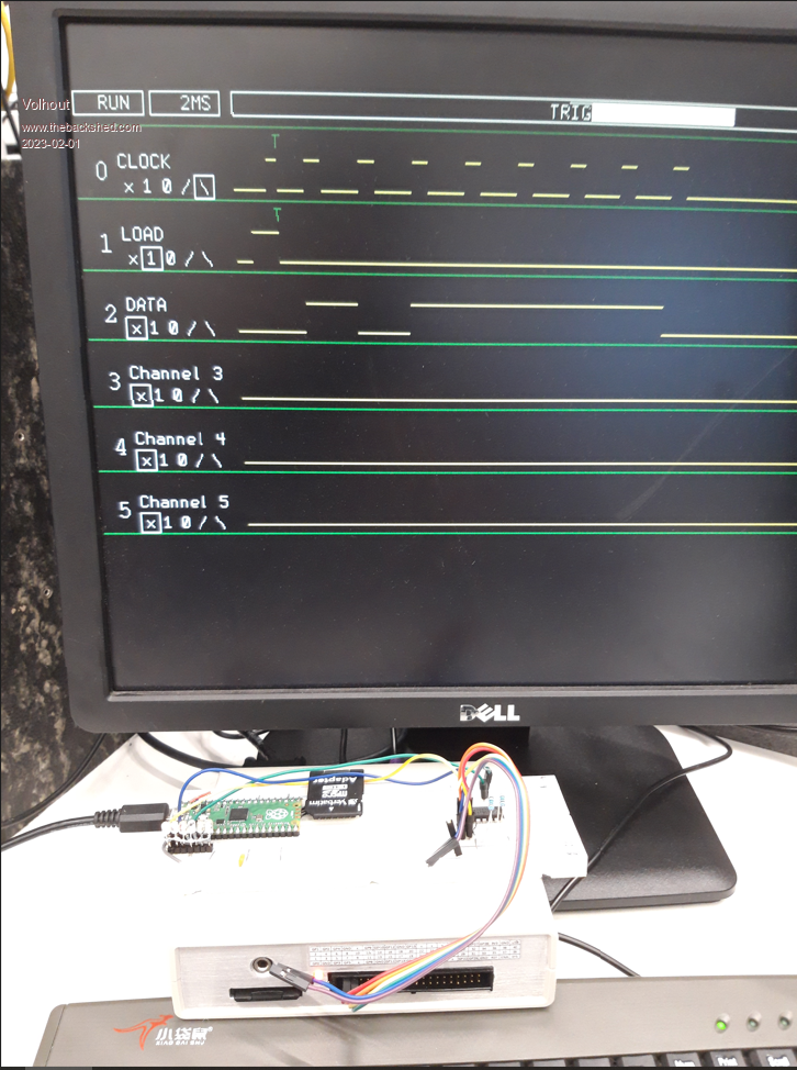 PicomiteVGA PETSCII ROBOTS |
||||
| matherp Guru Joined: 11/12/2012 Location: United KingdomPosts: 8592 |
This is looking really good  Couple of suggestions/ideas that may be useless/too difficult From a presentation perspective it would be great to have the vertical lines at signal transitions in the display If you are limiting to 8 channel (which I think is enough) why not change the dma to 8-bit? Likewise, do you really need to unpack at all? You could peek bytes out of the packed data and that way increase the amount of data you can store and work with massively. If you just need a second copy of the data in a different order you can use MEMORY COPY to move data from one array to another |
||||
| Mixtel90 Guru Joined: 05/10/2019 Location: United KingdomPosts: 5735 |
This is looking *really* nice. :) Just for additional prettyness (and because it means that you can use coloured clips on your test leads to make things less confusing) how about colouring the channel numbers? I think there's only red, green, yellow, blue, white & black commonly available but that's no matter. Some manufacturers don't have white available anyway. Edited 2023-02-01 19:51 by Mixtel90 Mick Zilog Inside! nascom.info for Nascom & Gemini Preliminary MMBasic docs & my PCB designs |
||||
| Volhout Guru Joined: 05/03/2018 Location: NetherlandsPosts: 3555 |
Hi Peter, Thank you for the compliment, but it is you who made it possible. Let me return the compliment !! Great work, and good support at my questions. - vertical lines at transitions: definitely do-able, will slow down a bit, but not too much. I have thought about several options before, including blitting small sprites, but line draw was simply fastest. Adding a few lines won't be that bad. - the 6/8 channel was a 15 channel before VGA mite, and I once mentioned a 32 channel (with external hardware). But for this VGA version it may be usefull to optimize. I will look into it. - Unpack.... I was lazy. The ring buffer stops at a random point. I use the unpack to change the ring into a linear file with first sample (in time) at address 0. If I set my mind to it, I can come up with math that can work from the packed circular file. Early versions have this. But when I added zoom it was easiest to work from a linear file. Volhout P.S. Thinking ahead: when running on a standard picomite and MMB4W user interface, what is the fastest way to transfer the packed file (16kbyte) from pico to PC ? Any suggestion ? PicomiteVGA PETSCII ROBOTS |
||||
| Pluto Guru Joined: 09/06/2017 Location: FinlandPosts: 330 |
Just tested LA V0.14. I had a very enjoyable ride! The UI is nice and intuitive. One thing that I miss (or maybe I missed it?) is the ability to move the trigger location. For serial decoding with more than 3 byte long sequences, it would be good to have the possibility to trigger very close to the left side of the screen. Then it would be possible to use higher sampling frequency (and get better resolution for decoding). I made a quick and dirty trigger change in V0.12 version, but it would be nice to have it via the UI. Sub init_memory ........ posttrigger% = samples% *9/10 'set trigger in beginning of circular buffer. Originally It was posttrigger% = samples%/2. (The "T"-mark however remained at center of the screen.) /Pluto |
||||
| Volhout Guru Joined: 05/03/2018 Location: NetherlandsPosts: 3555 |
Hi Pluto, The change you made is the correct one. Only in the "scrnprint" sub you have to change 'print the traces on the serial output Sub scrnprint st%,sp% 'print section st% to sp% of the linear array to serial (screen) Local z%,y%,x%,stp%,mask%,one%,eras%,bit%,trig% trig%=samples%-posttrigger% stp%=Int(0.5+(sp%-st%)/128) ' Timer =0 For j%=0 To max_chan_no% z%=j%*48+85 mask%=2^j% Box 112,z%-17,524,14,,1,1 'erase For i%=st% To sp% Step stp% bit%=((unpacked%(i%) And mask%)=0) one%=20*bit% Eras%=20*(1-bit%) x%=116+4*(i%-st%)/stp% y%=z%+one% Line x%,y%,x%+4,y%,,0 y%=z%+eras% Line x%,y%,x%+4,y%,,1 If i%>=trig% and i%<(trig%+stp%) And tr%(j%)<>0 Then Print @(x%-4,z%-17) "T" end if Next i% Next j% 'Print @(570,0) Timer End Sub Then it should work... Volhout Edited 2023-02-02 01:31 by Volhout PicomiteVGA PETSCII ROBOTS |
||||
| Pluto Guru Joined: 09/06/2017 Location: FinlandPosts: 330 |
Hi Volhout, some further testing of LA V0.14. Been working on SPI decoding. As a test device I have used MCP23S17 16-Bit I/O Expander with Serial Interface (SPI). The LA is just hooked up on the lines (CS, CLK, MOSI and MISO) between MCP23S17 and the "SPI"- PicoMite (standard green Pico). Testing with 100kHz SPI. For the LA I am using one of the "clones" (black with a WS2912 on board). Running at 378MHz w/o any problems. 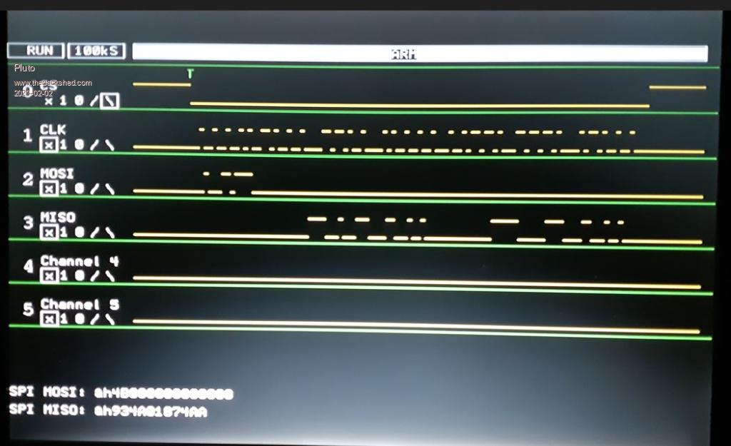 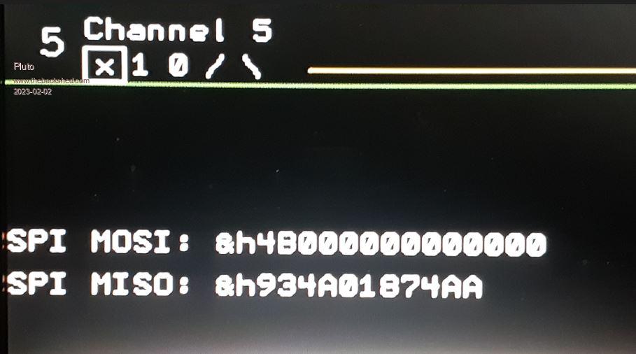 I just added the SUB call for the decoder into LA's main loop: 'display the data scrnprint st%,sp% SPI_mode0_decoder Loop End To start with I have focused on SPI mode 0. The code is still a mess with many fruitless routes commented out. Need some housekeeping before publishing. I works at least for the case I have tested with various number of bytes involved. Works as long as the whole "CS low" part fits into the buffer (unpacked%()). The decoding results are "live" and changes according to the visible plots on screen. Quite easy to use thanks to your brilliant UI. The LA will become a very useful tool. My PicoScope has only 2 channels; not too easy to use for SPI. My old USBee LA has enough channels, but operation is not very smooth and it is sometimes difficult to find the part of the graphs that are of interest. It is a Chinese clone!  (When do you think we will find a chinese clone of your LA?) (When do you think we will find a chinese clone of your LA?)/Fred /Fred |
||||
| Pluto Guru Joined: 09/06/2017 Location: FinlandPosts: 330 |
Serial decoder for SPI, mode 0 and mode 3. Instructions in my previous post. Here is the SUB: SUB SPI_mode0and3_decoder 'Total lenght of SPI transmission can be max 8bytes(=64 bits). 'mode 0: Clock is active high, data is captured on the rising edge (leading edge). 'mode 1: Clock is active low, data is captured on the rising edge (trailing edge). ' 'Setup: Channel 0: CS, Channel 1: CLK, Channel 2: MOSI (TX), Channel 3: MISO (RX) ' CSlow%=0 'location for CS going low, datacapture starts at this index in Unpacked%() CShigh%=0 'location for CS going high for ii%=1 to samples%-2 'find CS low area if (Unpacked%(ii%) and &b1)=0 and (Unpacked%(ii%-1) and &b1)=1 then CSlow%=ii%:end if IF (Unpacked%(ii%) and &b1)=1 and (Unpacked%(ii%-1) and &b1)=0 then CShigh%=ii%:end IF NEXT ii% IF CSlow%=0 or CShigh%=0 then 'Need to exit. Else too many error codes and LA stop. print @(0,420);"SPI data not found. Start and End of ChipSelect=Low have to be " print @(0,440);"detected. Changed sampling rate might help. Trigger on Chan 0. " EXIT sub 'No valid data found end if 'print"CSlow%:";CSlow%;" CShigh%:";CShigh% TXb%=1 'Transmitted bit (MOSI) RXb%=1 'Received bit (MISO) TXinvData%=0 'TX data with reversed bit ordeder (as collected) RXinvData%=0 'RX data with reversed bit ordeder (as collected) SPIbits%=0'nbr of bits in "SPI OPEN speed, mode, bits". Can be any number in the range of 4 to 16 bits. For ii%=CSlow%-1 to CShigh%+1 ' Unp0%=Unpacked%(ii%-1) 'Short form for the data Unp1%=Unpacked%(ii%) ' c0%=(Unp0% and &b10)>>1 'CLK @ present-1 .("previous" value in unpacked%() c1%=(Unp1% and &b10)>>1 'present TXdat0%=(Unp0% and &b100)>>2 ' TX DATA @ present-1 TXdat1%=(Unp1% and &b100)>>2 ' present RXdat0%=(Unp0% and &b1000)>>3 ' RX DATA @ present-1 RXdat1%=(Unp1% and &b1000)>>3 ' present 'mode 0: Clock is active high, data is captured on the rising edge IF c0%=0 and c1%=1 then 'rising CLK edge TXb%=TXb%+1 'Collect the data. The data will end up in "reverse" order. Need to 'change the order when all data is collected. TXinvData%=TXinvData%+(TXdat1%<<(TXb%-2)) 'eval dist between CLK pulses. Longer gaps indicate nbr of bits in 'TX (4 to 16 bits); nbr of bits in "SPI OPEN speed, mode, bits". 'CLKtiming0% is the previous index nbr unpacked%(n-1) IF TXb%=1 then CLKtiming0%=ii% end if IF TXb%>1 then Delta_ii1%=ii%-CLKtiming0% 'nbr of datapoints between CLK pulses CLKtiming0%=ii% 'value for next round 'Print "D_ii1:";Delta_ii1%;" D_ii0:";Delta_ii0% 'When a longer gap is detected we can calculate the SPIbits%. if Delta_ii1%>1.5*Delta_ii0% and TXb%>2 and SPIbits%=0 then SPIbits%=TXb%-2 'Print "SPI bits:";SPIbits% end if Delta_ii0%=Delta_ii1% '"normal" distance between CLK pulses. END IF end if ' IF c0%=0 and c1%=1 then 'rising CLK edge RXb%=RXb%+1 RXinvData%=RXinvData%+(RXdat1%<<(RXb%-2)) end IF next ii% TXdata%=0 'print "TXinvData%=";bin$(TXinvData%,TXb%-1) 'print "RXinvData%=";bin$(RXinvData%,RXb%-1) 'Change bit order for TX TXdata%=0 TXb%=TXb%-1 FOR ii%=1 to TXb% TXdata%=TXdata% OR ((TXinvData%>>(ii%-1)) and &b1)<<(TXb%-ii%) NEXT ii% 'pRINT "TX data:";BIN$(TXdata%,TXb%) 'Change bit order for RX RXdata%=0 RXb%=RXb%-1 FOR ii%=1 to RXb% RXdata%=RXdata% OR ((RXinvData%>>(ii%-1)) and &b1)<<(RXb%-ii%) NEXT ii% 'PRINT "RX data:";BIN$(RXdata%,RXb%) if SPIbits%=0 then exit sub 'nbrBytes%=RXb%/SPIbits% print @(0,420);"SPI MOSI: " print @(0,420);"SPI MOSI: &h";hex$(TXdata%) print @(0,440);"SPI MISO: " print @(0,440);"SPI MISO: &h";HEX$(RXdata%) END SUB /Pluto NB: @Volhout, when LA is started it shows 100k, but I believe it is starting at a different sample rate (10k)? (It is not a problem, easy to just press + or - and the new rate seems to correspond with the displayed sample rate.) |
||||
| Volhout Guru Joined: 05/03/2018 Location: NetherlandsPosts: 3555 |
Hi PLuto, Several small fixes: 1/ "t" will toggle the trigger between 12%, 50% and 87%, the trigger location is also visible in the zoom bar. 2/ vertical lines in the waveforms (Peter's suggestion) 3/ unroll fix (1 sample was sometimes fault when glueing waveform together). Regards, Volhout P.S. I am bothered by the keyboard. It is somtimes missing keystrokes. Have to look into that. LA15.zip Edited 2023-02-02 23:58 by Volhout PicomiteVGA PETSCII ROBOTS |
||||
| Pluto Guru Joined: 09/06/2017 Location: FinlandPosts: 330 |
Volhout, thank you for the update. I will immediately test. I have also from time to time problems with non-responding keyboard. Mostly fixed by unplugging and reconnecting. Mine is an old IBM 5V keyboard. Static electricity? Quite low humidity. SPI testing on LA V0.14 shows +90% of time correct, but occasionally there is a disturbance. Might be due the fault you detected in glueing together. /Pluto |
||||
| Pluto Guru Joined: 09/06/2017 Location: FinlandPosts: 330 |
Hi Volhout, the vertical lines make it much easier to follow the graph.  Trigger operation SPI-decoding is very stable now. I thought my earlier disturbances vere due to my breadboarding. If Peter got what he suggested, may I suggest a vertical cursor line? It would be very useful when checking synchronisation between the channels. (I guess it has to be green??) /Fred |
||||
| Volhout Guru Joined: 05/03/2018 Location: NetherlandsPosts: 3555 |
I added a feature I think is pretty usefull: measuring time User interface: press "m" for "measure" The sampling will halt, and the centre portion of channel 0 will be highlighted. When edges are detected, the time between edges is calculated from the sampling frequency of the logic analyzer. arrow keys change channel or next edges "m" exits the measurement mode. The time measured is calculated from the samples in memory. When sampling at 1 miliseconds, the resolution will be in miliseconds. The screen resolution may not show the time measured accurately because zoom may hide details. The red color depends on the edges of the underlaying tiles, and will not line up with the edges of the signal. But you get an idea. 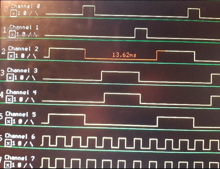 Here is the code (version 0.16) LA_16.zip Happy playing... P.S. about the cursor... it will not look nice, since the underlying tiles are 16x16, so you will get a 16 pixel wide mis-coloured band. I can do it, but it will look uggggly. To get an idea: run LA_16, type <CTRL-C>, then CLS<CR>. The tiles that make up the screen. Edited 2023-02-03 07:17 by Volhout PicomiteVGA PETSCII ROBOTS |
||||
| Volhout Guru Joined: 05/03/2018 Location: NetherlandsPosts: 3555 |
Getting there..... A nice name for the program... 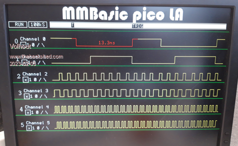 @Pluto: any idea when you can add the decoders (I2C and SPI) ? Do you feel a bit confident about them ? Volhout PicomiteVGA PETSCII ROBOTS |
||||
| IanT Regular Member Joined: 29/11/2016 Location: United KingdomPosts: 84 |
This is looking really good now. Going to have to build one. Well done - tremendous work from everyone (apart from me I'm afraid) Thank you very much. Regards, IanT |
||||
| Pluto Guru Joined: 09/06/2017 Location: FinlandPosts: 330 |
Volhout, I have the SPI (mode 0&3) decoder as ready as I am able to get it. You know best how to add them to the UI. sub SPI_mode0and3_decoder 'Total lenght of SPI transmission can be max 8bytes(=64 bits). 'mode 0: Clock is active high, data is captured on the rising edge (leading edge). 'mode 1: Clock is active low, data is captured on the rising edge (trailing edge). ' 'Setup: Channel 0: CS, Channel 1: CLK, Channel 2: MOSI (TX), Channel 3: MISO (RX) ' CSlow%=0 'location for CS going low, datacapture starts at this index in Unpacked%() CShigh%=0 'location for CS going high for ii%=1 to samples%-2 'find CS low area if (Unpacked%(ii%) and &b1)=0 and (Unpacked%(ii%-1) and &b1)=1 then CSlow%=ii%:end if IF (Unpacked%(ii%) and &b1)=1 and (Unpacked%(ii%-1) and &b1)=0 then CShigh%=ii%:end IF NEXT ii% IF CSlow%=0 or CShigh%=0 then 'Need to exit. Else too many error codes and LA stop. print @(0,420);"SPI data not found. Start and End of ChipSelect=Low have to be " print @(0,440);"detected. Changed sampling rate might help. Trigger on Chan 0. " EXIT sub 'No valid data found end if 'print"CSlow%:";CSlow%;" CShigh%:";CShigh% TXb%=1 'Transmitted bit (MOSI) RXb%=1 'Received bit (MISO) TXinvData%=0 'TX data with reversed bit ordeder (as collected) RXinvData%=0 'RX data with reversed bit ordeder (as collected) SPIbits%=0'nbr of bits in "SPI OPEN speed, mode, bits". Can be any number in the range of 4 to 16 bits. For ii%=CSlow%-1 to CShigh%+1 ' Unp0%=Unpacked%(ii%-1) 'Short form for the data Unp1%=Unpacked%(ii%) ' c0%=(Unp0% and &b10)>>1 'CLK @ present-1 .("previous" value in unpacked%() c1%=(Unp1% and &b10)>>1 'present TXdat0%=(Unp0% and &b100)>>2 ' TX DATA @ present-1 TXdat1%=(Unp1% and &b100)>>2 ' present RXdat0%=(Unp0% and &b1000)>>3 ' RX DATA @ present-1 RXdat1%=(Unp1% and &b1000)>>3 ' present 'mode 0: Clock is active high, data is captured on the rising edge IF c0%=0 and c1%=1 then 'rising CLK edge TXb%=TXb%+1 'Collect the data. The data will end up in "reverse" order. Need to 'change the order when all data is collected. TXinvData%=TXinvData%+(TXdat1%<<(TXb%-2)) 'eval dist between CLK pulses. Longer gaps indicate nbr of bits in 'TX (4 to 16 bits); nbr of bits in "SPI OPEN speed, mode, bits". 'CLKtiming0% is the previous index nbr unpacked%(n-1) IF TXb%=1 then CLKtiming0%=ii% end if IF TXb%>1 then Delta_ii1%=ii%-CLKtiming0% 'nbr of datapoints between CLK pulses CLKtiming0%=ii% 'value for next round 'Print "D_ii1:";Delta_ii1%;" D_ii0:";Delta_ii0% 'When a longer gap is detected we can calculate the SPIbits%. if Delta_ii1%>1.5*Delta_ii0% and TXb%>2 and SPIbits%=0 then SPIbits%=TXb%-2 'Print "SPI bits:";SPIbits% end if Delta_ii0%=Delta_ii1% '"normal" distance between CLK pulses. END IF end if ' IF c0%=0 and c1%=1 then 'rising CLK edge RXb%=RXb%+1 RXinvData%=RXinvData%+(RXdat1%<<(RXb%-2)) end IF next ii% TXdata%=0 'print "TXinvData%=";bin$(TXinvData%,TXb%-1) 'print "RXinvData%=";bin$(RXinvData%,RXb%-1) 'Change bit order for TX TXdata%=0 TXb%=TXb%-1 FOR ii%=1 to TXb% TXdata%=TXdata% OR ((TXinvData%>>(ii%-1)) and &b1)<<(TXb%-ii%) NEXT ii% 'pRINT "TX data:";BIN$(TXdata%,TXb%) 'Change bit order for RX RXdata%=0 RXb%=RXb%-1 FOR ii%=1 to RXb% RXdata%=RXdata% OR ((RXinvData%>>(ii%-1)) and &b1)<<(RXb%-ii%) NEXT ii% 'PRINT "RX data:";BIN$(RXdata%,RXb%) if SPIbits%=0 then exit sub 'nbrBytes%=RXb%/SPIbits% print @(0,420);"SPI MOSI: " print @(0,420);"SPI MOSI: &h";hex$(TXdata%) print @(0,440);"SPI MISO: " print @(0,440);"SPI MISO: &h";HEX$(RXdata%) END sub The I2C is technically ready. It contains a lot of "debugging" prints (which have to be removed) and misses still the "print @" statements to get the results on screen. Unfortunately I an just now going for a trip abroad for almost 1 week and I have not time to make these final changes before I leave. I can however post the code as is for your consideration to make the housekeeping and add to the LA or wait until I am back. Sub I2C_decoded 'Assumes that I2C-clock is on Channel 0 and I2C-data on channel 1. Print "Sampling rate=";sr$(frequency_index%) ON ERROR SKIP 1 dim bits%(10) 'Collected bits in received byte. bit%=0 'bit number 1...8. Bit 1 is MSB. Collect%=0 'Set to 1 after START bit and stays at 1 until 8 bits are collected. Addr=0 'I2C address. Full address is 7bit Addr+R/Wbit WR=1 'WRITE or READ bit expected for ii%=1 to samples%-2 Unp0%=Unpacked%(ii%-1) 'The 2 LSB of these are also printed in order to see that Unp1%=Unpacked%(ii%) 'correct clock transitions are happening. c0%=Unp0% and &b01 'CLK @ present-1 .("previous" value in unpacked%() c1%=Unp1% and &b01 'present d0%=(Unp0% and &b10)>>1 'DATA @ present-1 d1%=(Unp1% and &b10)>>1 'present 'START: Falling DAT while CLK stays high. IF c0%=1 and c1%=1 and d0%=1 And d1%=0 then Collect%=1 'Start collecting 8 bits print "*****************************************************************" Print "START, Dat:";Dat;" Unp0 :";BIN$(unp0%,2);" Unp1 :";BIN$(unp1%,2);" ii%:";ii% end if 'Read one bit when CLK has changed from low to high IF c0%=0 and c1%=1 and Collect%=1 then inc bit% 'present bit. Bits 1...8 contain valid data. if bit%=1 then print "- - - - - - - - - - - - - - - - - - - - - - - - - - - - - - - -" end if IF Bit%<=7 then 'first 7 bits IF bit%>1 then 'just used for debugging: check if the bits come regularily. Do not trust it for bit 1 and 2! Deltaii%=ii%-ii0% ii0%=ii% 'store the index for calculation of CLK rise-to-rise for valid data end if print "Dat CLK^:";d1%;" bit:";bit%;" Unp0 :";BIN$(unp0%,2);" Unp1 :";BIN$(unp1%,2);" ii%:";ii%;" Deltaii%=";Deltaii% bits%(bit%)=d1%':print "bits%(bit%)=";bits%(bit%) Addr=Addr+(bits%(bit%)<<(7-bit%)) 'keep the accumulated value for the I2C-address. END if IF Bit%=8 and d1%=0 and WR=1 then 'bit 8 can be data or READ/WRITE bit: Here it is WRITE (=0) print "Dat CLK^:";d1%;" bit:";bit%;" Unp0 :";BIN$(unp0%,2);" Unp1 :";BIN$(unp1%,2);" ii%:";ii%;" Deltaii%=";Deltaii%; " WRITE addr: &h";HEX$(Addr) 'WR=0 '?bits%(1);bits%(2);bits%(3);bits%(4);bits%(5);bits%(6);bits%(7);" ";bits%(8);bits%(9) END if IF Bit%=8 and d1%=1 and WR=1 then 'READ bit (=1) print "Dat CLK^:";d1%;" bit:";bit%;" Unp0 :";BIN$(unp0%,2);" Unp1 :";BIN$(unp1%,2);" ii%:";ii%;" Deltaii%=";Deltaii%;" READ addr: &h";HEX$(Addr) 'WR=0 END if IF Bit%=8 and WR=0 then 'Not a READ/WRITE: DATA-bit 8 bits%(bit%)=d1%':print "bits%(bit%)=";bits%(bit%) Addr=(Addr<<1)+bits%(bit%) 'Addr is now the value of the byte print "Dat CLK^:";d1%;" bit:";bit%;" Unp0 :";BIN$(unp0%,2);" Unp1 :";BIN$(unp1%,2);" ii%:";ii%;" Deltaii%=";Deltaii%;" Byte is:";hex$(addr) WR=0 END if 'ACK/NACK: bit nbr 9 after START IF bit%=9 then Print "- - - - - - - - - - - - - - - - - - - - - - - - - - - - - - - -" print "Dat CLK^:";d1%;" bit:";bit%;" Unp0 :";BIN$(unp0%,2);" Unp1 :";BIN$(unp1%,2);" ii%:";ii%;" Deltaii%=";Deltaii%;" ACK/NACK=";d1% bit%=0 WR=0 Addr=0 end if 'IF bit%>9 then ' print "Dat CLK^:";d1%;" bit:";bit%;" Up:";BIN$(unpacked%(ii%),4);" ii%:";ii% 'end if end if ' 'STOP: rising Dat while CLK stays high if c0%=1 and c1%=1 and d0%=0 and d1%=1 then Collect%=0:bit%=0:Addr=0 Print "STOP, Dat:";d1%;" Unp0 :";BIN$(unp0%,2);" Unp1 :";BIN$(unp1%,2);" ii%:";ii% Print "------------------------------------------------------------------------------------" WR=1 Addr=0 end if Next ii% End sub /Pluto |
||||
| Martin H. Guru Joined: 04/06/2022 Location: GermanyPosts: 904 |
wow this together in a case with an 8' POS Display VGA Monitor like this  and you have a "standalone Unit" Edited 2023-02-04 01:33 by Martin H. 'no comment |
||||
| Volhout Guru Joined: 05/03/2018 Location: NetherlandsPosts: 3555 |
For those who want to try the first instance of the I2C decoder, try attached version. OPTION CPUSPEED 252000 for best experience. At 126 MHz the PS2 keyboard is not working optimal. To be fixed.... I2C decoder works best if you have sampling at 500kS or higher. You have to connect SCL to GP0 and SDA to GP1 for this version. Trigger: SCL="1" and SDA if falling edge ("\") Best if you do single trigger ("s"), and when HALT shows top left corner, press the "i" button and wait. You will see green text aligned with the traces on the screen. The characters "S" (start), "P" (stop), "R" (read), "W" (write), "A" (acknowledge) and "N" (not-acknowledged) are official I2C lables. The adress is in 7 bit notation. The data in 8 bit notation. You can zoom in with the cursor keys. Exit I2C decoder mode with the "i" button. Press "r" for repeat triggering. LA_21_banner.zip Place both files in the same folder on the SD card of the VGA picomite. This is what it looks like...  This version does not (yet) provide framing error warnings in case data is corrupted. So you will not be warned in case there are any. Improvements may come in the future. This decoder is based on PLUTO's work (although re-written to include synchronisation with the actual samples). All credit goes to him... Edited 2023-02-07 08:09 by Volhout PicomiteVGA PETSCII ROBOTS |
||||
