
|
|
Forum Index : Microcontroller and PC projects : Need help with control for push/pull mosfets
| Page 1 of 2 |
|||||
| Author | Message | ||||
| Frank N. Furter Guru Joined: 28/05/2012 Location: GermanyPosts: 1102 |
Hello to all, I have a +5V/GND square wave voltage which I want to convert to a +/-12V square wave voltage using two mosfets. 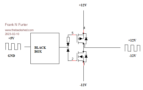 My attempts under LTspice to control the mosfets with transistors have not worked so far - can anyone help me? Many thanks! Frank |
||||
| Volhout Guru Joined: 05/03/2018 Location: NetherlandsPosts: 5931 |
Hi Frank, What is the desired switching frequency, what are the FET's you envision. Are the -12V and +12V hard DC voltages, or is there ripple. IS the system switching continuous when operating, or is there a requirement that it could be static -12V or static +12V (can you use AC-coupling to the gates of the FET's). Do you need a "hobby" solution or something ribust that can be used in customer application ? Regards, Volhout PicomiteVGA PETSCII ROBOTS |
||||
| Frank N. Furter Guru Joined: 28/05/2012 Location: GermanyPosts: 1102 |
Hi Volhout, thanks for your response! At the moment it is solved via an operational amplifier. Unfortunately, this does not work rail-to-rail and suitable operational amplifiers are currently not readily available (and/or very expensive). However, voltages as close as possible to + and - 12V are needed. The space on the board is also very limited!  Only a maximum of +/- 12mA at 1 kHz switching frequency is required. There is also a state where +12V are output continuously instead of switching (this is the OFF state). Usually I use the IRLML5203TRPBF as P-FET and the IRLML0030TRPBF as N-FET. I don't know yet which FET's would be best for this application.... And yes, I need a robust solution that can be used in a customer application. Frank |
||||
| Mixtel90 Guru Joined: 05/10/2019 Location: United KingdomPosts: 8911 |
I don't suppose 5V GND can be common to -12V by any chance can it? That would simplify things a lot. Otherwise I suspect you'll be stuck with the op-amp or some sort of isolated driver. Maybe opto-coupling? Mick Zilog Inside! nascom.info for Nascom & Gemini Preliminary MMBasic docs & my PCB designs |
||||
| matherp Guru Joined: 11/12/2012 Location: United KingdomPosts: 11512 |
LM393B ? |
||||
| Volhout Guru Joined: 05/03/2018 Location: NetherlandsPosts: 5931 |
 The 1kHz can be handled by a comparator. If you use a LM393 it will sink below 1V to switch off the -12V N-channel FET. It needs a pullup to reach the +12V. With 6mA sink capability, you can go as low as (12+12)/0.006=4k ohm. I used 4.7k This is a very simpel circuit. Since there is a moment in time where both FET's are conducting (when the output if the comparator is between -7V and +7V) there will be peak current in the FET's and power supply. To limit this current the 12 ohm resistor is added. Be aware that this circuit drives the gates between 0V an (12+12)V. So you need to use FET's that can handle 30V as Vgs. Also for the P-FET. The comparator input compares the LOGIC IN signal with 2.5V. That is half the voltage of the 5V. 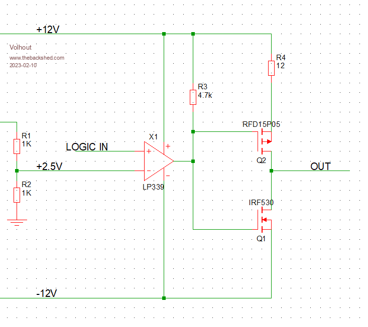 Regards, Volhout P.S. the circuit can be enhanced and tuned by using the other half of the LM393 dual comparator and an externa transistor. But that may not be needed. PicomiteVGA PETSCII ROBOTS |
||||
| phil99 Guru Joined: 11/02/2018 Location: AustraliaPosts: 3290 |
Adding to Volhout's circuit switch-on delays to reduce the need for R4. The values of the resistors will depend on the gate capacitance and the required delay, which should be slightly longer than the switch off time. I guess the circuit simulator can work it out. 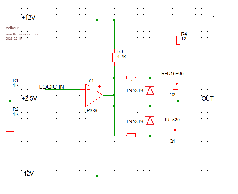 |
||||
| Frank N. Furter Guru Joined: 28/05/2012 Location: GermanyPosts: 1102 |
Hmm, this looks very similar to the current realization: 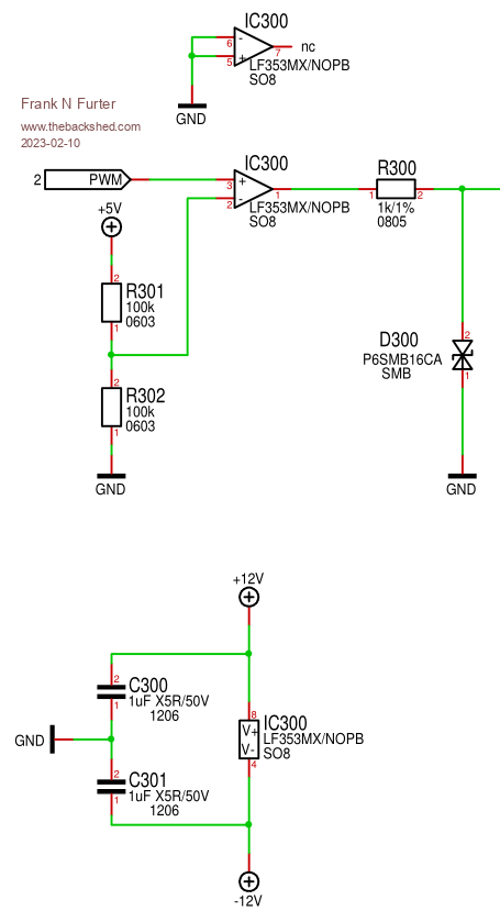 Unfortunately I don't have room to put the LM393B and the mosfets.  Is there no possibility to do without the LM393B and to realize it with transistors? Internally, it is also only set up as an open collector: 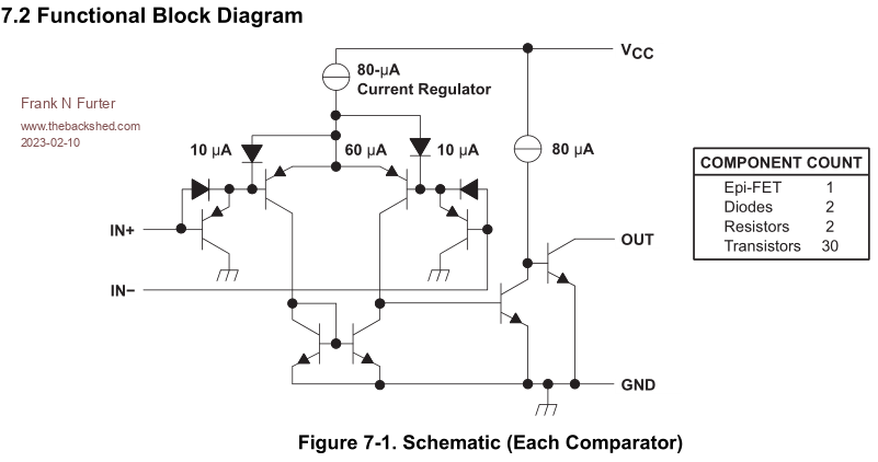 Frank |
||||
| Mixtel90 Guru Joined: 05/10/2019 Location: United KingdomPosts: 8911 |
Opto-isolator with transistor output. Mosfet gates have a resistor up to +12 and the opto down to -12. The Pico output is simply the opto input via a resistor. Two resistors and a 6-pin DIL. Should be fine well over 1kHz. Done. :) Ok, you'll get a little dissipation in the mosfets during the switching time of the opto (they can be pretty fast though) but if that's of concern your mosfets aren't big enough or need a heatsink. You also have the option of isolating the control and output voltages completely if you wish. Mick Zilog Inside! nascom.info for Nascom & Gemini Preliminary MMBasic docs & my PCB designs |
||||
| Volhout Guru Joined: 05/03/2018 Location: NetherlandsPosts: 5931 |
@mixtel90: analog optoisolators are not fast enough. Digital opto isolators may work fine (i.e. Toshiba TLP2745 (totempole output) can be powered from +12V and GND and drive the P-FET, powered between GND and -12V and drive the N-FET). The LF353 is a poor choice. At +/-12V the output can go from +10V to -10V. It may not turn off the FET completely. It is fast though (for an OPAMP). Edited 2023-02-10 23:12 by Volhout PicomiteVGA PETSCII ROBOTS |
||||
| Frank N. Furter Guru Joined: 28/05/2012 Location: GermanyPosts: 1102 |
@Volhout: The LF353 IS currently the operational amplifier - it generates a signal from about +11.4V to -10.4V (WITHOUT additional mosfets). I would need a bit more voltage in the negative range... @Mixtel90: I had just tried that with the opto. In the simulation it seems to work - I would have in any case no place for it!  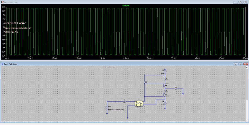 The OPA2171AID would probably work in my current circuit (without mosfets) - unfortunately it's poorly available (and too expensive)... Frank |
||||
| circuit Guru Joined: 10/01/2016 Location: United KingdomPosts: 305 |
Do you actually need separate + and - 12 volt feeds? Would a simple H-bridge not do the trick - just reversing the single 12 volt feed at 1KHz is so easy. At the low current that you require you could switch it with a single L293D chip. Edit; furthermore, a quick check shows that this is one chip that does not seem to be in short supply. Edited 2023-02-11 01:31 by circuit |
||||
| Volhout Guru Joined: 05/03/2018 Location: NetherlandsPosts: 5931 |
The L293 is far worse than the current LF353 opamp. The outputs cannot drive rail to rail, and since you have a bridge (using 2 outputs) the problem doubles. 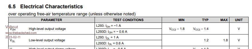 PicomiteVGA PETSCII ROBOTS |
||||
| Volhout Guru Joined: 05/03/2018 Location: NetherlandsPosts: 5931 |
What about some classic bipolar junction transistor fun... This is super simple, super cheap, but may require board area you do not have... Although in SMT parts (dual transistors in SOT23-6) and small 0603 resistors... No FET's, just use the transistors to drive the 12mA 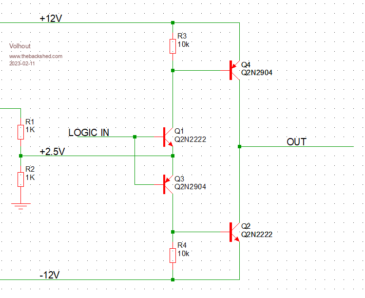 This will work with 5V and also with 3.3V.... As long as you keep the resistors 1k and 10k Regards, Volhout Edited 2023-02-11 01:52 by Volhout PicomiteVGA PETSCII ROBOTS |
||||
| Mixtel90 Guru Joined: 05/10/2019 Location: United KingdomPosts: 8911 |
I suspect that even a 6N138 would be plenty fast enough for 1kHz. Probably 10kHz. However, if there's no board space then it's immaterial. :) It's about the same space as an op-amp unless you are thinking SMD. Mick Zilog Inside! nascom.info for Nascom & Gemini Preliminary MMBasic docs & my PCB designs |
||||
| Frank N. Furter Guru Joined: 28/05/2012 Location: GermanyPosts: 1102 |
This is a very interesting circuit, thank you! However, in the simulation I achieve only a little less than -10V and about +11V.  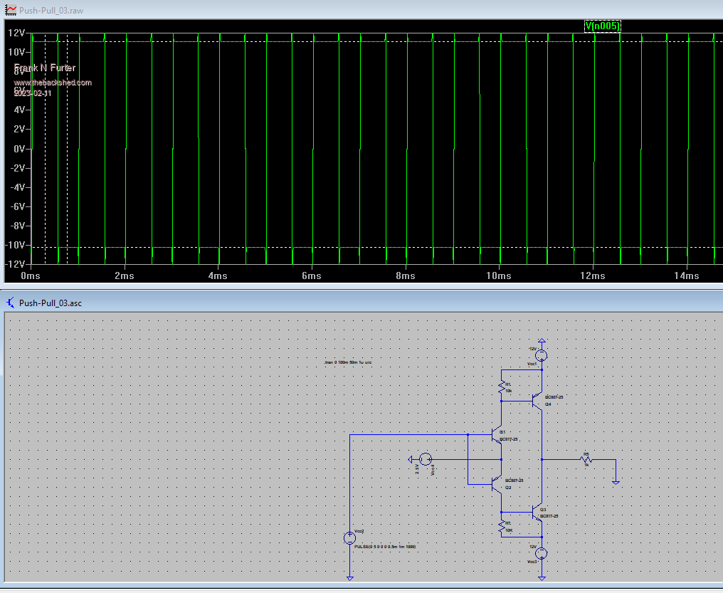 I tried it with BC807 an BC817... Frank |
||||
| Volhout Guru Joined: 05/03/2018 Location: NetherlandsPosts: 5931 |
Hi Frank, Please use BC557 and BC547. The BC807 and BC817 are darlingtons, and do not work well in this circuit. Or use: NPN: BC548, BC549, BC550, BC337 PNP: BC558, BC559, BC560, BC327 Succes PicomiteVGA PETSCII ROBOTS |
||||
| phil99 Guru Joined: 11/02/2018 Location: AustraliaPosts: 3290 |
Hi Frank, In your simulation of Volhout's circuit you have omitted the source resistance of the 2V5 supply (1k / 2 = 500R). that is important as it sets the base current for the output transistors. My experience with similar circuits suggests you should get within 0.3V of the 12V rails. Edit PN100 / PN200 transistors have a Vce(sat) of 150mV @ Ic = 100mA or Vce(sat) of under 50mV @ Ic = 10mA Should give you 11.94V or better at 12mA. . Edited 2023-02-11 09:13 by phil99 |
||||
| Frank N. Furter Guru Joined: 28/05/2012 Location: GermanyPosts: 1102 |
@Volhout: Darlingtons??? The BC807 is the SMD form of BC327 and the BC817 of BC337... (the selection of transistors is unfortunately very limited in my program...) @phil99: THAT'S IT!!! YOU ARE RIGHT! For simplicity I just took a voltage source with 2,5V - if I put a voltage divider to 5V it works!!!! 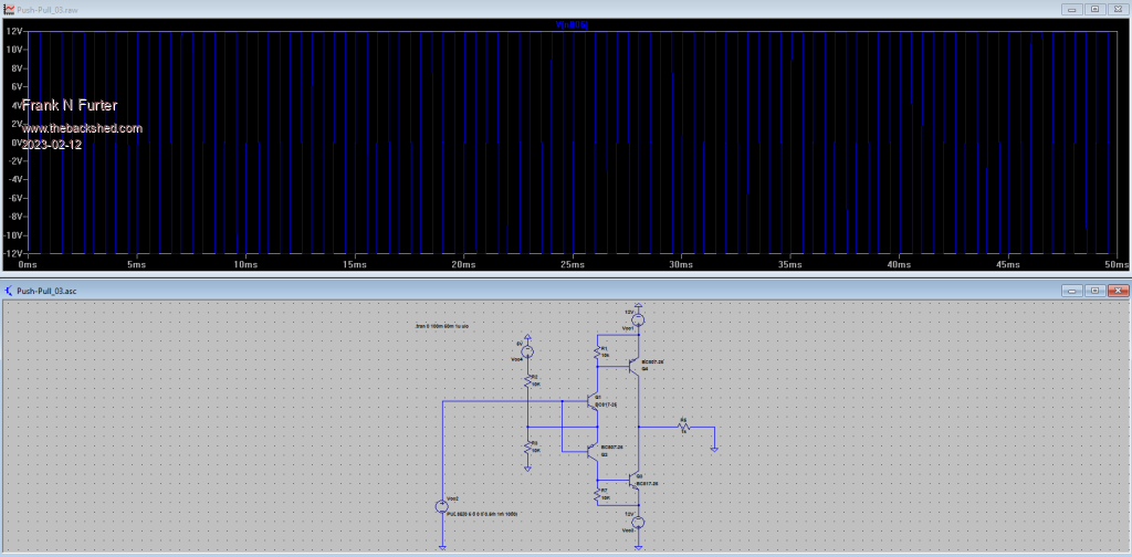 Thank you both so much!!! Frank |
||||
| Volhout Guru Joined: 05/03/2018 Location: NetherlandsPosts: 5931 |
Sorry Frank, you are right. The 807 and 817 are not darlingtons. Wrong memory... Good luck with the circuit. Volhout PicomiteVGA PETSCII ROBOTS |
||||
| Page 1 of 2 |
|||||
| The Back Shed's forum code is written, and hosted, in Australia. | © JAQ Software 2026 |
