
|
|
Forum Index : Microcontroller and PC projects : PicoMiteVGA PS/2 KB - MOSFET
| Page 1 of 2 |
|||||
| Author | Message | ||||
| JohnS Guru Joined: 18/11/2011 Location: United KingdomPosts: 4335 |
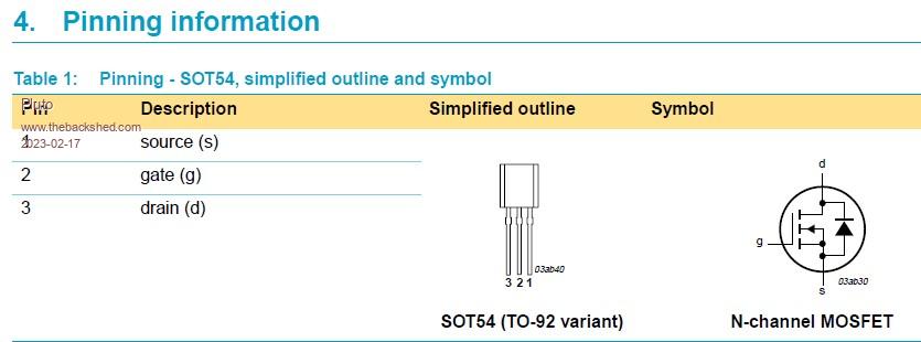
The MOSFETs for the keyboard (Design #2) was to have used BST72A (two). Various others seem OK, but are the source, gate, drain sometimes in the reverse order? E.g. 2N7000, TN0702N3-G, VN0808L-G, VN10KN3-G all seem the same but opposite of BST72A. (I've not found a convincing pinout for the BST72A, though.) John |
||||
| Pluto Guru Joined: 09/06/2017 Location: FinlandPosts: 411 |
 |
||||
| Amnesie Guru Joined: 30/06/2020 Location: GermanyPosts: 757 |
I am using the 2N7000, not because it is better but it is far more available where I live and yes the pinout is "inversed". But the datasheet tells you anyways... Greetings Daniel |
||||
| Mixtel90 Guru Joined: 05/10/2019 Location: United KingdomPosts: 8904 |
In theory the 2N7000 is a bit marginal but I've never had a problem with them. They are very cheap and easy to get. Mick Zilog Inside! nascom.info for Nascom & Gemini Preliminary MMBasic docs & my PCB designs |
||||
| stanleyella Guru Joined: 25/06/2022 Location: United KingdomPosts: 2807 |
I used these fine for kb.. but then found the kb worked on 3.3V and didn't need the converter, doh! https://www.ebay.co.uk/itm/154677844601?hash=item2403849a79:g:CTkAAOSw9cxi8YGK&amdata=enc%3AAQAHAAAAoPDnzrgHwgmouI4NGNQJvoSpUuPbecitnqtnFVtANHl16K1YQg79mJVAUxetEeTTY1IY7oFP6HUf5pMjfx%2FMkgc9ijmboJquM9SFND%2BoDTdEsxlYh2f3zAOI9KRZoAUhYbc57hXxDScwfIIQ71MSMvh2Y7UHoWMmGZZ2vxKtKo5kknxO%2BKrM2jqOjt%2FC734ki1vK5mdMNdsQWwMxC1jStYE%3D%7Ctkp%3ABk9SR-iD-q7LYQ |
||||
| Mixtel90 Guru Joined: 05/10/2019 Location: United KingdomPosts: 8904 |
No use for Design #2, Stan. They won't fit the PCB. :) Mick Zilog Inside! nascom.info for Nascom & Gemini Preliminary MMBasic docs & my PCB designs |
||||
| JohnS Guru Joined: 18/11/2011 Location: United KingdomPosts: 4335 |
I found the BST72A datasheet unclear & its pics unhelpful/unclear (e.g. no indication of the viewpoint). All the others were clear, with clear pics. Sadly that didn't help me compare because of the BST72A's pics etc. It did seem likely the pin order is reversed, but that in itself felt mad!! I mean, WTF! Thanks everyone, though. John |
||||
| JohnS Guru Joined: 18/11/2011 Location: United KingdomPosts: 4335 |
Aha. What makes them marginal? I.e. what spec should I worry about that makes them so? John Edited 2023-02-17 03:26 by JohnS |
||||
| matherp Guru Joined: 11/12/2012 Location: United KingdomPosts: 11499 |
VGS(th) higher than the spec in the Philips application note AN97055 |
||||
| Mixtel90 Guru Joined: 05/10/2019 Location: United KingdomPosts: 8904 |
VGS(th) - the gate threshold voltage. This is the gate voltage (relative to the source) where the device starts to conduct between the source and drain. <geeky bit> For the 2N7000 the typical value is 2.1v but it can vary between 1V and 3V. Just to make things interesting the value varies with temperature, increasing at low temperatures. The above voltages are quoted at a case temperature of 25C. So, if it is below 25C and you are unlucky enough to have a device at the top of its tolerance then it may need over 3V on the gate to switch on. That's a bit close on a 3V3 supply. We are helped out to some extent by the shape of the transfer characteristics. We are running them with a very low drain current, which puts VGS(th) towards the lower end of its tolerance band. It doesn't matter that we can't get much drain current - we don't want it. :) </geeky bit> Mick Zilog Inside! nascom.info for Nascom & Gemini Preliminary MMBasic docs & my PCB designs |
||||
| JohnS Guru Joined: 18/11/2011 Location: United KingdomPosts: 4335 |
Thanks! When I ordered (yesterday) I just guessed at a similar part they (Farnell) had in stock, VN0808L-G so I may be lucky? John Edited 2023-02-17 05:01 by JohnS |
||||
| phil99 Guru Joined: 11/02/2018 Location: AustraliaPosts: 3289 |
When checking the pin-out a multimeter may be quicker than searching datasheets. The body diode gives you D & S, so G is the other. For Vgs(th) use ohms range across D & S then apply 3V G-S and the resistance should drop below 1k. If not try another. Testing a 2N7000 that way gave 4R2 at 3V3 G-S Connecting a multimeter to a breadboard. Strip the ends of short pieces of single strand hookup wire, winding one end around the meter probe and plug the other into the breadboard. Edited 2023-02-17 15:06 by phil99 |
||||
| Volhout Guru Joined: 05/03/2018 Location: NetherlandsPosts: 5930 |
Indeed WTF There has been inconsistency between pinouts of plastic encapsulated transistors and FET's forever. The plastic (motorola) 2N2222 is reverse packaged compared to it's european (philips) counterparts as BC337/BC547. And this may also count for the FET's like BST72A and 2N7000. In modern packages this is more harmonized. The SOT23 package variants of these parts have the same pinout. It is just the TO92 parts that have this problem. Volhout PicomiteVGA PETSCII ROBOTS |
||||
| stanleyella Guru Joined: 25/06/2022 Location: United KingdomPosts: 2807 |
Why not the inverter I suggested for non pcb. I use an 8 channel one for spi glcd on pics. They work and are neat and cheap. |
||||
| matherp Guru Joined: 11/12/2012 Location: United KingdomPosts: 11499 |
It is exactly the same thing. The circuit on those inverter modules is the circuit in the PicoMiteVGA manual. I used one when prototyping during the original firmware development Edited 2023-02-18 03:03 by matherp |
||||
| Mixtel90 Guru Joined: 05/10/2019 Location: United KingdomPosts: 8904 |
Look at the first post of the thread, Stan. He's using Design #2, which is almost certainly on a pre-drilled PCB. That module simply won't fit mechanically. If he was using the Design #2 *circuit* on a breadboard then you'd be right - those little modules can be very convenient. I've used them on PCBs several times as well as on breadboards. Speaking of little modules, plugging normal male headers into a breadboard is one of the quickest ways I know of damaging them. The clips in the breadboard are simply not designed for pins that size. I've started using 0.6mm silver plated wire instead of headers for things that are going to be plugged into breadboards. Mick Zilog Inside! nascom.info for Nascom & Gemini Preliminary MMBasic docs & my PCB designs |
||||
| JohnS Guru Joined: 18/11/2011 Location: United KingdomPosts: 4335 |
I am. Thanks for that - I shall try to remember it. John |
||||
| stanleyella Guru Joined: 25/06/2022 Location: United KingdomPosts: 2807 |
I got that it's a pcb design. The pcbs I've used take those header pin size no problem. I use breadboard as it's quick and cheap and not permanent. looks a mess for glcd spi but neat for vga and fits in with my thoughts that picomite is a hobbyist idea that you can try cheaply to see if you like it. You'd learn more wiring it on breadboard. There was a video https://www.youtube.com/watch?v=kZaWYgIYgd8&t=1019s published on the forum which I thought was not a way to get a new user to use vga picomite... would take ages but a breadboard with the 4 resistor vga circuit would take minutes... ok a ps2 kb you should just happen to have and a vga monitor/tv but you get the idea of hobby/fun. If you don't like it then you haven't invested much. I think the idea is you have all the bits except the rpipico.  |
||||
| Mixtel90 Guru Joined: 05/10/2019 Location: United KingdomPosts: 8904 |
I'm not saying that header pins won't go into breadboard. They will. Often they will come out and go back in again, no problem. However, try putting a resistor lead into a hole that's had a header pin in it. There is far less contact pressure than that in a hole that has never had a header pin. That stretching of the springs is one-way - they can't recover. If you have a Pico that's simply left in the same board, or at least those particular holes are only ever used for header pins, then you may never notice the damage. Also, not all breadboards are equal. Some (usually much more expensive) will recover better than others. Also, breadboards have a current rating. That is decided by the contact pressure available. Obviously, once a spring has less pressure then it's current rating is reduced. Trying to put the same current through a low contact pressure leads to heating. That tempers the spring and reduces the pressure even more - there is a serious possibility of fire. That's why you should never use breadboards for power devices. If you can find current rating for cheap breadboards then ignore it and stick to about 100mA max. when its new. The Chinese production doesn't usually bother about such things, only about how many they can sell! Mick Zilog Inside! nascom.info for Nascom & Gemini Preliminary MMBasic docs & my PCB designs |
||||
| pwillard Guru Joined: 07/06/2022 Location: United StatesPosts: 340 |
Europe adopted a standard for semiconductor parts naming that was based on a pre-existing Philips standard used for vacuum tubes. These parts became known as the Pro Electron/EECAdesignation which was created in the mid 1960s. It used a much more informative prefix and suffix than the JEDEC standard used (JEDEC is where 1N for diodes and 2N for BJTs came from). Here is an example: 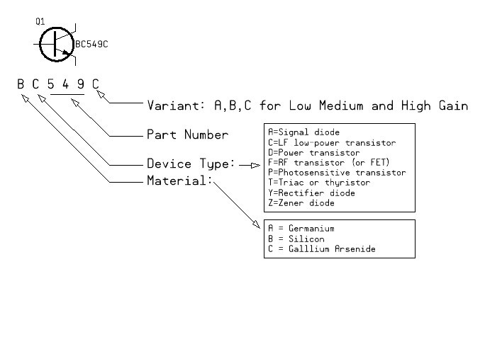 Interestingly, pretty much every 'BC' part has a flipped layout from JEDEC pinouts, and Japanese parts also tend to have a different layout than JEDEC parts. It's almost as if they are forcing you to *use their replacement parts* if your PCB was designed for them in the first place. Edited 2023-02-19 00:29 by pwillard |
||||
| Page 1 of 2 |
|||||
| The Back Shed's forum code is written, and hosted, in Australia. | © JAQ Software 2026 |
