
|
|
Forum Index : Microcontroller and PC projects : PicX UNO
| Author | Message | ||||
| Mixtel90 Guru Joined: 05/10/2019 Location: United KingdomPosts: 8911 |
Design Preview: Guess what size it is! ;) This is a prequel to the PicX that I posted recently. A little different. I've simplified things a bit, making it a bit cheaper and a bit less fiddly to build. It's probably better for beginners now. I decided to drop the PS/2 keyboard port. It's a "nice to have" but I don't think it's essential. I've also decided to not bother with a linear regulator, although 3V3_EN is available if the user wants to patch one in for a bit of low noise stuff. The same goes for VREF - you'd have to patch something in if you really needed it. Everything is there on the expansion module anyway. I kept the audio filter to pretty much the minimum for headphones. The socket can be isolated so the outputs can be used as PWM analogue outputs or connections can be made directly to the socket by the user. Might be useful for RX,TX,GND or something. The Expansion Module is simply a parallel socket with the PicoMite. Something that may appeal is the switchable joystick socket. This uses a single link to disconnect all the pull-up resistors so that the pins are freed off. It is pin-compatible with Port A of the PicoGAME and, if you add a single capacitor from GP14 to GND (which may not even be needed), it will also support the Game Pad on this port in the same way. Connections are there for both standard switched Atari joysticks and two analogue inputs for X and Y axis of an analogue stick. I'm still tweaking, so construction stuff coming later. 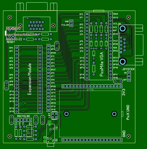 Mick Zilog Inside! nascom.info for Nascom & Gemini Preliminary MMBasic docs & my PCB designs |
||||
| JohnS Guru Joined: 18/11/2011 Location: United KingdomPosts: 4335 |
Er, I genuinely don't know :( The UNO must be a clue but...? What's the big rectangle at bottom right for? John |
||||
| Mixtel90 Guru Joined: 05/10/2019 Location: United KingdomPosts: 8911 |
Virtually all my boards are either 100mm x 100mm or cut out of that size now. It's the maximum "cheap rate" size at JLCPCB. :) The rectangle is a 170 pin breadboard - as used on the PicX, but this time there's only one, hence "UNO" (both the indefinate article - in some cases - and the number one in Italian). The female headers above and below it are power and gnd rails. The smaller box at the bottom left is the little RTC module. Mick Zilog Inside! nascom.info for Nascom & Gemini Preliminary MMBasic docs & my PCB designs |
||||
| JohnS Guru Joined: 18/11/2011 Location: United KingdomPosts: 4335 |
Thanks. The RTC modules I know don't have so many pins so which one please? John |
||||
| Mixtel90 Guru Joined: 05/10/2019 Location: United KingdomPosts: 8911 |
This sort. :) It goes over the top of the audio resistors so it's perhaps not so clear as it could be. Edited 2023-02-22 22:00 by Mixtel90 Mick Zilog Inside! nascom.info for Nascom & Gemini Preliminary MMBasic docs & my PCB designs |
||||
| JohnS Guru Joined: 18/11/2011 Location: United KingdomPosts: 4335 |
Oh, I did find that one, my mistake, sorry :( John |
||||
| al18 Senior Member Joined: 06/07/2019 Location: United StatesPosts: 238 |
Looks nice, except for the missing PS/2 port. Any chance you would consider adding it? |
||||
| Mixtel90 Guru Joined: 05/10/2019 Location: United KingdomPosts: 8911 |
I don't think so, mainly because of difficulty in fitting everything in. The only available area is pretty cramped. It also uses two IO pins that would need links to isolate them if it's not required. It would probably be possible to put one on the expansion socket anyway, along with its level shifting components, if required. I've managed to fir a microSD socket now but, of course, with no card in and no configuration then all four pins are available to the user. At the moment only the six pins used for VGA are tied up (and the two audio pins are of little use, granted). The user has control over everything else and can choose to tie things in if they wish. Mick Zilog Inside! nascom.info for Nascom & Gemini Preliminary MMBasic docs & my PCB designs |
||||
OA47 Guru Joined: 11/04/2012 Location: AustraliaPosts: 1050 |
Wondering if a sea of holes could be placed under the expansion area so that additional bits could be attached with or without the expansion board ? (Would cover the PS2 port if required) OA47 Edited 2023-02-23 12:10 by OA47 |
||||
| Mixtel90 Guru Joined: 05/10/2019 Location: United KingdomPosts: 8911 |
The things I put myself though for you lot.... The weather wasn't too good so I took a lesson from the Peter Mather book of design:  Mick Zilog Inside! nascom.info for Nascom & Gemini Preliminary MMBasic docs & my PCB designs |
||||
| Volhout Guru Joined: 05/03/2018 Location: NetherlandsPosts: 5931 |
@Mick, An UNO (Arduino UNO) is 54mm x 65mm. I have the feeling your definition of UNO is more that of One Square Decimeter...  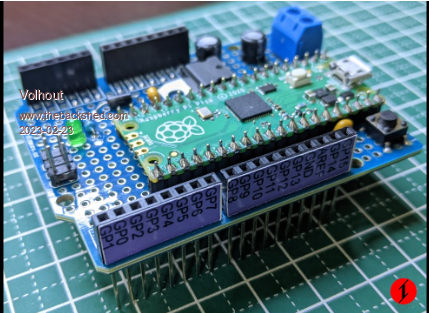 Volhout Edited 2023-02-23 23:07 by Volhout PicomiteVGA PETSCII ROBOTS |
||||
| Mixtel90 Guru Joined: 05/10/2019 Location: United KingdomPosts: 8911 |
I carefully counted the breadboards on mine and reached a grand total of UNO. :) Mick Zilog Inside! nascom.info for Nascom & Gemini Preliminary MMBasic docs & my PCB designs |
||||
| al18 Senior Member Joined: 06/07/2019 Location: United StatesPosts: 238 |
Looking good - thanks for adding the PS/2 port. |
||||
| The Back Shed's forum code is written, and hosted, in Australia. | © JAQ Software 2026 |
