|

|
Forum Index : Microcontroller and PC projects : Design #3 - PicoMite VGA mini
| Author | Message | ||||
| Mixtel90 Guru Joined: 05/10/2019 Location: United KingdomPosts: 5710 |
I'm never *really* happy with my designs. :) At some point I have to admit that I must end the intellectual challenge and create Gerbers, but it's like tearing part of me away! I love designing this stuff. I don't like mounting parts on the bottom of the board. Firstly, it feels like cheating to me and secondly it can make assembly more difficult than it needs to be. An exception can be made sometimes if you want space on top of the board by mounting a surface-mount SD socket on the bottom. I did one design like this where I surface mounted the PicoMite on the top side. When I start to lay out a board, before a single trace is defined, I find that there's a particular arrangement that is probably going to work and several that won't for some reason. I pick out the ones that are likely to lead to the shortest track lengths as being the best candidates. I rarely have to move things round much once I start doing the traces. Perhaps nudge something to make a little more space but that's about it usually. However, I do tend to move things to make them more aesthetically pleasing to my eye! Not sure what you mean, sorry. Mick Zilog Inside! nascom.info for Nascom & Gemini Preliminary MMBasic docs & my PCB designs |
||||
| JanVolk Regular Member Joined: 28/01/2023 Location: NetherlandsPosts: 95 |
Mick, Top and bottom same island pattern and interconnected for strength, so that the islands do not come loose after a number of times soldering. Jan |
||||
| Mixtel90 Guru Joined: 05/10/2019 Location: United KingdomPosts: 5710 |
No PCBs are really suitable for repeated soldering. The plating through the holes is just that - it's not heavy duty copper. You can interconnect top and bottom areas though. I put a through-hole pad on then set it's isolation distance to zero. The pads then effectively become part of the copper areas. You can increase the current capacity of THP holes by filling them with solder, of course. Note tha it is very difficult to solder onto backplanes as the heat is conducted away too fast. That's why "thermal pads" are used, which only connect to the backplanes using narrow strips of copper. EDIT: It won't be long now, honest. :) I've moved the Reset button to the other side, allowing lower connectors (probably the short turned pin ones) to be used for the PicoMite so that the USB socket stands more chance of being accessible through the case. I've also added a pull-up on the reset line, which I'd completely forgotten about. . Edited 2023-03-09 01:55 by Mixtel90 Mick Zilog Inside! nascom.info for Nascom & Gemini Preliminary MMBasic docs & my PCB designs |
||||
| paceman Guru Joined: 07/10/2011 Location: AustraliaPosts: 1326 |
Mick, I'm not sure whether you may already have done it (C11?) but is it worthwhile including the .01uF cap from pin 30 (RUN) to GND as suggested by Phill99 and endorsed by Volhout here. Greg |
||||
| Mixtel90 Guru Joined: 05/10/2019 Location: United KingdomPosts: 5710 |
I stuck with the resistor as it's a pain to find space now! If it's found to be needed then it's easy enough to put one underneath the board. Personally, I've never had problems with the reset line so I have no experience of glitches on it. Perhaps I'm lucky? I suppose I could change the resistor into a capacitor with a bit of fiddling. I'll look at that. C11 is a 3V3 supply decoupler (now next to H1). I'd like to have got another in closer to K5 really... EDIT: Done it. C12 to ground from RUN pin. You can use either the resistor, the capacitor, both or neither now, depending on how insecure you are feeling. :) . Edited 2023-03-09 19:05 by Mixtel90 Mick Zilog Inside! nascom.info for Nascom & Gemini Preliminary MMBasic docs & my PCB designs |
||||
| paceman Guru Joined: 07/10/2011 Location: AustraliaPosts: 1326 |
I knew you could :) I haven't had a problem with it either but it seemed like a good idea given those gents had had problems and seemed to know what they were talking about. I put a cap under my 'standard' VGA board back when it was mentioned, just as you suggested. It was a doddle with a 0.2" lead spacing cap that I already had a bag of - and doesn't even protrude past the cut off pin ends. Greg |
||||
| Mixtel90 Guru Joined: 05/10/2019 Location: United KingdomPosts: 5710 |
Having done only one impossible thing today I thought I should do another, so C13 is now a decoupler next to K5. :) I'm saving up... Douglas Adams - HHGTTG Mick Zilog Inside! nascom.info for Nascom & Gemini Preliminary MMBasic docs & my PCB designs |
||||
| lizby Guru Joined: 17/05/2016 Location: United StatesPosts: 3012 |
Are the mills still grinding, or are we close to gerber time? PicoMite, Armmite F4, SensorKits, MMBasic Hardware, Games, etc. on fruitoftheshed |
||||
| thwill Guru Joined: 16/09/2019 Location: United KingdomPosts: 3838 |
Lance, I sometimes think your addiction to ordering PCBs almost matches Mick's addiction to designing them  . But I guess we each have our own cross to bear ... I've just ordered yet another (hopefully) different NES controller from AliExpress in my search for the Holy Grail. . But I guess we each have our own cross to bear ... I've just ordered yet another (hopefully) different NES controller from AliExpress in my search for the Holy Grail.Best wishes, Tom Edited 2023-03-10 02:36 by thwill Game*Mite, CMM2 Welcome Tape, Creaky old text adventures |
||||
| Mixtel90 Guru Joined: 05/10/2019 Location: United KingdomPosts: 5710 |
Very close now, I think, Lance. :) I'm probably out tonight, so tomorrow is quite likely. I've just been doing some of the updates to the manual. By the way, Ton, it would be pretty trivial to use a switched or analogue joystick with this. GP0-GP3 for directions, GP4 for Fire, GP26 and GP27 for the Y and X analogue inputs. No space for a DB9 socket though so it would have to be an external adapter. Mick Zilog Inside! nascom.info for Nascom & Gemini Preliminary MMBasic docs & my PCB designs |
||||
| lizby Guru Joined: 17/05/2016 Location: United StatesPosts: 3012 |
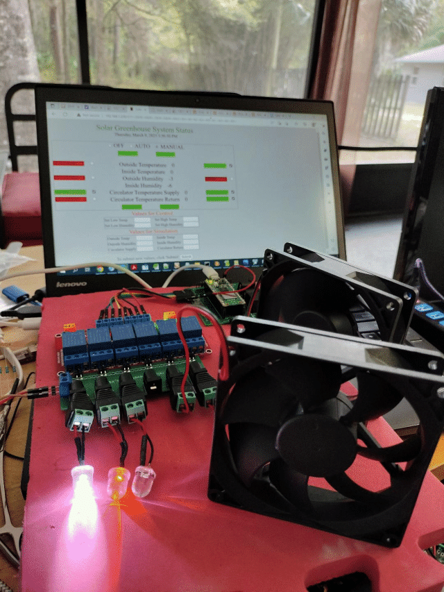
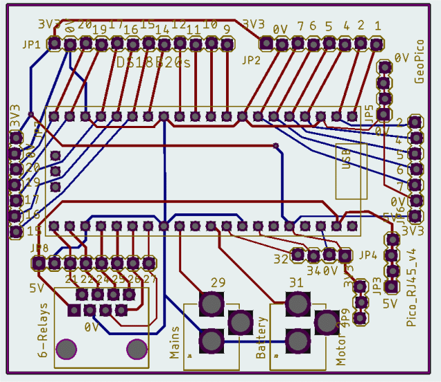
Well, Tom, I did just yesterday order version 4 of the PCB I'm calling GeoPico (because it started off being the controller for Paul_L's geothermal system, and might just make it there someday):  I'm not really into VGA (have only built Mick's mini version so far), but the PCBs are so cheap, why not. If anyone in the U.S. wants one of Mick's new offering, I figure I'll have 3 of the 5 to spare, maybe 4 of them.  ~ Edited 2023-03-10 06:57 by lizby PicoMite, Armmite F4, SensorKits, MMBasic Hardware, Games, etc. on fruitoftheshed |
||||
| Mixtel90 Guru Joined: 05/10/2019 Location: United KingdomPosts: 5710 |
For some reason I can't upload the zip of the construction pack. I'm getting a 413 "too large" error but it's only 1.16MB. :( Anyway, it's now available from the link in my sig. Look for "Mixtel90's PCBs / PicoMiteVGA_mini6_Construction_Pack.zip". No, it wouldn't upload without the underscores either before anyone asks. Mick Zilog Inside! nascom.info for Nascom & Gemini Preliminary MMBasic docs & my PCB designs |
||||
| paceman Guru Joined: 07/10/2011 Location: AustraliaPosts: 1326 |
I had the same problem uploading last night. Tried to upload a .jpg (1.4MB) and it complained with the 413 'too large', so I cut it back to a teensy 148 KB .jpg and it still complained with 413. |
||||
| PilotPirx Regular Member Joined: 03/11/2020 Location: GermanyPosts: 66 |
@Mixtel90 Thanks for the great design. I have ordered my boards from JLCPCB and am anxiously awaiting them. When I have them I will create a case for 3D printing. |
||||
| lizby Guru Joined: 17/05/2016 Location: United StatesPosts: 3012 |
Ordered from JLCPCB for $6.34USD, paypal & slow boat shipping. Thanks very much for your efforts. PicoMite, Armmite F4, SensorKits, MMBasic Hardware, Games, etc. on fruitoftheshed |
||||
| Pluto Guru Joined: 09/06/2017 Location: FinlandPosts: 329 |
Just ordered from JLCPCB for $7.66 including shipping and tax (required for import to EU). $6.17 w/o tax. Thanks Mick! /Pluto |
||||
| Mixtel90 Guru Joined: 05/10/2019 Location: United KingdomPosts: 5710 |
I thought I'd better get some too. Have to keep JLCPCB in business, don't we? :) I found the most awkward thing to source was the VGA connector. I couldn't find them here in the UK but I got a few of them from China some time ago. Mick Zilog Inside! nascom.info for Nascom & Gemini Preliminary MMBasic docs & my PCB designs |
||||
| JohnS Guru Joined: 18/11/2011 Location: United KingdomPosts: 3650 |
Will Farnell 2401182 fit? If not, what's not right about it? John |
||||
| Mixtel90 Guru Joined: 05/10/2019 Location: United KingdomPosts: 5710 |
No. It's too deep front to back. Look at the photo in my manual, there's not much gap between the socket metalwork and the rear row of pins. Something like these. Mick Zilog Inside! nascom.info for Nascom & Gemini Preliminary MMBasic docs & my PCB designs |
||||
| JohnS Guru Joined: 18/11/2011 Location: United KingdomPosts: 3650 |
Thanks. John |
||||