
|
|
Forum Index : Microcontroller and PC projects : Considerations for a potential "EduMite"
| Author | Message | ||||
| thwill Guru Joined: 16/09/2019 Location: United KingdomPosts: 3839 |
My 2c, A sandwich of two PCB's, one functional and the other purely structural held together with nylon screws and spacers makes for a cheap, rigid, if porous enclosure - which can have important setup instructions silk-screened onto it as part of the process. The next price bracket above that would be an attractive acrylic sandwich like my PicoGAME VGA enclosure: 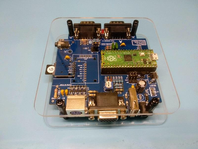 Best wishes, Tom Edited 2023-03-22 05:06 by thwill Game*Mite, CMM2 Welcome Tape, Creaky old text adventures |
||||
| thwill Guru Joined: 16/09/2019 Location: United KingdomPosts: 3839 |
And 1c more, IMO It's worth bearing the lesson of the ZX Spectrum Next in mind. I think it took them 3-5 years to go from working internals to a cased unit at £200+ each (and I believe they lost money on every unit) - you aren't looking for anything as fancy, but it might be considered an indicator of what is required for a small-run custom cased device. Tom Edited 2023-03-22 05:28 by thwill Game*Mite, CMM2 Welcome Tape, Creaky old text adventures |
||||
| matherp Guru Joined: 11/12/2012 Location: United KingdomPosts: 8578 |
That sort of approach is certainly more feasible. For me the most critical aspect is that all components are soldered to the PCB and so can be mass-produced without significant labour. Spring loaded connectors like this 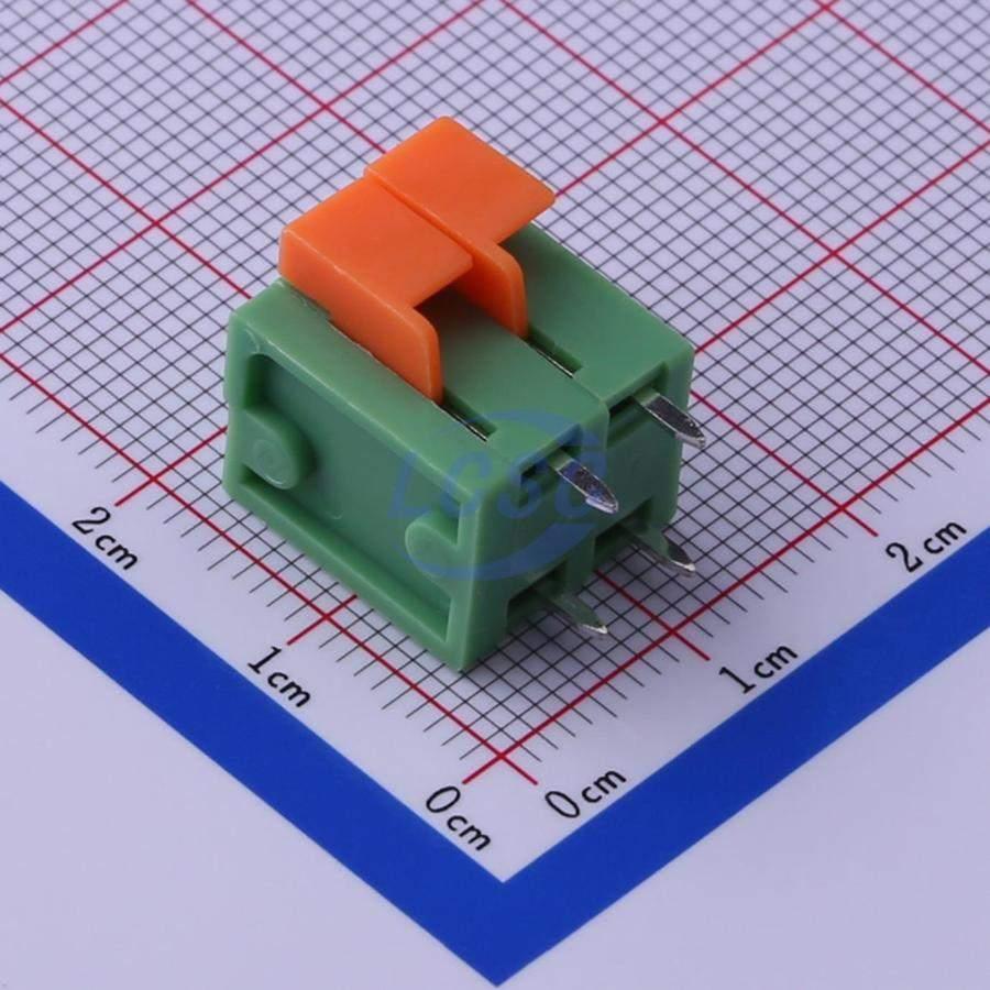 allow bare wire connections and can be used repeatedly. We need to discuss the requirements for a display: seven segment, 1602, colour. price increases left to right and robustness decreases. Ease of use decreases, wow factor increases |
||||
| Volhout Guru Joined: 05/03/2018 Location: NetherlandsPosts: 3519 |
Peter, No idea about cost of such connectors, but (at the moment) nothing beats pin headers and cheap (female) dubro connector wires. When they get unreliable, throw them away. The dubro wires are not bad, but most users use the male version in combination with the (horrible contacts) breadboards. But the female ones, in combination with pin headers provide relatively good connection at an unbeatable price. Volhout Edited 2023-03-22 05:58 by Volhout PicomiteVGA PETSCII ROBOTS |
||||
| JohnS Guru Joined: 18/11/2011 Location: United KingdomPosts: 3655 |
Robust / safe enough for kids? John |
||||
| lizby Guru Joined: 17/05/2016 Location: United StatesPosts: 3013 |
I'm assuming "dubro" wires are what are also called dupont wires. I agree about ease of use. For a picomite experimenter board, there's always this, including a small I2C display: 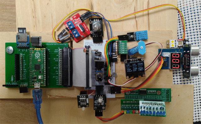 PicoExperimenter PCB (Link with link to youtube video) Includes I2C, SPI, rotary encoder, SSD1306 I2C LCD, 3-color LED, LED flashing, Buzzer, I2C MCP23017 flashing 16 LEDs, Servo slewing from full clockwise to full counter-clockwise and back, PWMing of 5V LED using MOSFET module, Dimming/brightening of 5V LED using MOSFET module using potentiometer, ultrasonic distance measuring module. An ILI9341 or ILI9488 could be mounted, but that would take away pins. This "hat" PCB could be mounted on the 2x20 header on on Mick's new VGA PCB (not yet with Gerbers). The GPIO pins are different, but that would just be a software change. Some pins would not be available if VGA is used. PicoMite, Armmite F4, SensorKits, MMBasic Hardware, Games, etc. on fruitoftheshed |
||||
| JohnS Guru Joined: 18/11/2011 Location: United KingdomPosts: 3655 |
Er... with a child age 10? Tom's construction looks plausible (maybe?) John Edited 2023-03-22 07:16 by JohnS |
||||
| Nimue Guru Joined: 06/08/2020 Location: United KingdomPosts: 367 |
Fair comment - I see the "issue" with mounting to the enclosure -- in my imagination, the exact case from the CMM2, with sockects / leds etc drilled and mounted to the case itself and connected the PCB/board via "long" jumper wires of some description. 3D printing is possibly an option - and certainly for small scale / prototyping (ie I have one personally, secondary schools will have more than one - and increasingly primary schools do.) From a perspective of functionality as long as the screen/panel was secured in some way and the PCB had rubber feet to make it secure and non "slippy" then I suppose an open PCB does introduce the concept of using the device to identity what is what component -- especially if the PCB silkscreen is suitably verbose. Entropy is not what it used to be |
||||
| Nimue Guru Joined: 06/08/2020 Location: United KingdomPosts: 367 |
^^^ This would work a treat -- and attach sockects etc to the "top" plate. Entropy is not what it used to be |
||||
| Nimue Guru Joined: 06/08/2020 Location: United KingdomPosts: 367 |
(1)seven segment... I imagine the device being coded to display voltage as part of a set of experimetns (2) Not a fan personally as I always find them hard to use -- but would allow the flexibility of multi line (and basic) graphics / icons --- display voltage on multiple pins / status of a switch / status of an LED etc etc (3) Would be ideal as the kiddos could also "code" / draw to the LCD panel in some manner --- but realistically, this is probably not going to happen in the timescales available. I suppose this is what I was considering initially -- those 1" Waveshare panels. (2) Is probably the sweet spot of price / functionalt << the blue screen ones are nice N Entropy is not what it used to be |
||||
| Nimue Guru Joined: 06/08/2020 Location: United KingdomPosts: 367 |
Connectors? Kiddos use banana plugs in much of the kit designed for schools -- plus they are likely to have the leads with the male versions on. Those spring loaded terminal types are also fine to connect bare wires. What they cant be doing with (no fine motor skills) are those terminal blocks with screws in --- they can never ever get the wire in and screw it back down. Much of the Microbit kit gets round all this with extra large plated holes on the PCB onto which crocodile clips can be attached to make a connection. N Entropy is not what it used to be |
||||
| Nimue Guru Joined: 06/08/2020 Location: United KingdomPosts: 367 |
I like it -- clear acrylic would allow the components to be seen and refereed to. Plus would be "easier" to service if needed. N Entropy is not what it used to be |
||||
| Nimue Guru Joined: 06/08/2020 Location: United KingdomPosts: 367 |
One of the biggest supplier of this kind of kit to education is Kitronik and one the more "robust" manufacturers is "Monks Makes" (as in Mr Monks makes....) Have a look here: Example kit This for example shows the through hole plated connectors that are common for use in class.... which is a perfect segue into the "ecosystem" we could build --- not thinking commerically here -- more like make the designs available and build some should schools want to go that way.... 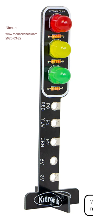 Edit: The more I look at what school's pay for -- the more it makes me want to make alternatives -- (this one is not actually badly priced) -- but they intend it to be physically bolted to the microbit -- so impractical to designed a functional 4 - junction --- you'd need 4 microbits (so total price circa £120) -- achievable with one EduMite and 4 sets of traffic lights. N Edited 2023-03-22 08:03 by Nimue Entropy is not what it used to be |
||||
| thwill Guru Joined: 16/09/2019 Location: United KingdomPosts: 3839 |
Hmm, I don't think you could cheaply attach sockets to the top plate of acrylic if that's what you mean, though I've seen similar enclosures where there are cut outs in the acrylic to reach the components (usually buttons) on the PCB. I think Peter is sensibly pushing a design which JLPCB could basically manufacture in its entirety out of PCB and Chinesium and "you" would only be left with a bit of basic mechanical assembly to do yourself or farm out. That means every component is soldered to PCB and nothing is bolted/glued/selotaped to any enclosure. This is the very early stages of the PicoGAME LCD Mk2 prototype, just two PCBs held together with 4 nylon spacers, it's completely rigid and feels suprising substantial. 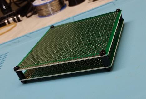 In my case I will only be sticking the battery and speaker between the PCBs and all the active stuff: LCD, buttons, Pico (under the LCD) and audio "tank farm" will be mounted on the top board and completely unprotected from sticky fingers. In your case the two boards could be connected by male/female header pairs as well as the spacers (c.f. the red ILI9341 modules can be mounted to a PCB) and all the delicate gubbins mounted in the interior on the bottom PCB. The top PCB could then have any user accessible sockets, buttons, display, etc. mounted to it. If the display needs extra protection then I would consider having the top in two pieces half acrylic (it's just a rounded rectangular piece with some mounting holes) and half PCB and then mounting the display to the bottom PCB under the acrylic. Of course I recognise I'm just making s**t up based on the only two electronics projects I've ever been involved in  . .Best wishes, Tom Edited 2023-03-22 08:46 by thwill Game*Mite, CMM2 Welcome Tape, Creaky old text adventures |
||||
| Nimue Guru Joined: 06/08/2020 Location: United KingdomPosts: 367 |
Likewise -- different between my own tinkering and this. I now get what Peter was on about -- yes, in the first instance this would be "me" assembling to try some in class -- so as much as possible fabbed onto the board at PCB stage is the way forward -- in this example you present - the top pcb could be protoboard style to allow components to be added / connected underneath with drilling holes etc (ie I could manage that ;-) ) Simple is the key - and willing to sacrifice things. At a basic leve1: (1) Simple!! (2) Some form of integrated display (3) LDR / DHT22 built in (4) On board switches hardwired to i/o (5) On board LEDs (x3) hardwired OR WS2812B (6) Piezo sounder / buzzer (7) Some way to break out the remaining i/o (8) Enclosed in some manner --- like your examples N Entropy is not what it used to be |
||||
| tgerbic Newbie Joined: 25/07/2019 Location: United StatesPosts: 40 |
I hate to say this but this thread sounds like designing a universal vehicle that gets 100 miles per gallon, can carry 12 people and 2000 pounds of sand, but will fit in a garage built for a honda civic. Though it has been a while since creating hardware and courseware to teach technical subjects, I think I can suggest a better approach. First you need to decide what you want to specifically teach for different groups of students. Using a US education system grades for an example. In the elementary school (probably second grade to sixth grade) group, a certain set of skills should be taught. Middle school (possibly six to eight grade) a more complex set of things. Then high school (nineth to twelfth grade) would be more complex. Maybe even tie the middle and high school skills to some science fair program to give a compelling direction for the students to actually learn and accomplish something. Some students will be a little behind or advanced in the program so some latitude for levels should be accounted for. This is why I suggest splitting the skills into three or four buckets and making the trainer board somewhat modular. Now knowing what you want to teach in each bucket, what the general mass of students may be able to learn and build (technically and physically), you can figure out what must be on the basic board and what might be plug-ins. The basic board might need to be similar to the old Heathkit 6800 trainer, with a couple more sensors and maybe a two line LCD. The board may then be expandable with a set of connectors for plug in modules or an edge connector to plug in an expansion module with more complex displays, connectors and such. It should be possible to attach a bluetooth module and a serial to USB module in order to allow some remote I/O but not depend on it to be able to do some general tasks. USB and/or a thumb drive might be the best way to get programs from a laptop to the board itself. To some extent, the Arduino style boot loader would be useful here, or the ability to just import from a thumb drive for a bit more flexibility. Building a board that is fairly simple and straightforward, with bounds, would make it significantly easier for a young person to understand, and not be completely overwhelmed and maybe give up. Also this may bound the amount of knowledge the teaching staff must learn and use to support younger students. Another advantage to a basic board with expansion relates to cost and complexity. For different grades or schools, they can buy only as much as needed for teaching at their grade levels. This helps contain the costs to the school system. Another advantage to this is that the trainer board set stays familiar to the students as they progress through the program. Switching platforms often means besides all the learning the student has to do, they need to relearn the underlying hardware/system. This also makes it harder for the teaching staff to learn the system and support the students. Plug boards should be considered with simple solid wire jumpers of various lengths. Consider that onboard, hardwired, devices offer little flexibility and no education around really "building" something, or allow for adding random components to try other things. Alligator clips to components often make a wiring nightmare and are prone to shorts when bumped. The smaller grippers are mostly poor quality these days, delicate, and pop off when moving things around. Both of these can be very frustrating for younger students to build circuitry around and troubleshoot. Building a general course structure and then building the required hardware to teach it is probably better long term. If you don't know what you need to teach or how it will be taught opens the hardware up to too many parts, interfaces, complexity, too much for the teaching staff to learn, and cost the school system may not be able to budget for. These are just some quick thoughts based on my experience training mostly grade school kids and company repair techs. |
||||
| phil99 Guru Joined: 11/02/2018 Location: AustraliaPosts: 1781 |
With the acrylic sandwich. (2) Some form of integrated display - Protected under acrylic. (5) & (6) On board LEDs (x3) hardwired OR WS2812B - Ditto (4) & (7) Some way to break out the remaining i/o - extend the PCB beyond one or two sides of the acrylic with 4mm plated-through holes for banana plugs and crocodile clips. 3V3 output fed from a separate current limited regulator to prevent crashes when they short it. 220R series resistors on all i/o for same reason. |
||||
| tgerbic Newbie Joined: 25/07/2019 Location: United StatesPosts: 40 |
To amplify phil99's comment, some care needs to be taken to prevent over voltage, over current and shorts. Blowing up boards can be a problem. Frustrated students with unknown board problems just makes things worse. Failing boards, which must be replaced, just adds more cost to the program and may add resistance to buying the boards in the first place. |
||||
| tgerbic Newbie Joined: 25/07/2019 Location: United StatesPosts: 40 |
Another thing to consider it that any pin that would be placed to hook an alligator clip to must be isolated from other circuitry that could be shorted by the edges of the alligator clip moving around. All connectors must be horizontally attached and very easy to disconnect. It should be expected that any cables sticking out will get accidentally pulled out while moving books, laptops, backpacks, etc. around the desktop. Polarity sensitive connections must be keyed or polarity protected. I guess you could call this adding some kid-proof design to the board. |
||||
| lizby Guru Joined: 17/05/2016 Location: United StatesPosts: 3013 |
Now there's a way to call for that "universal vehicle that gets 100 miles per gallon, can carry 12 people". How many of the modules which have been called for as "plug-ins" have that kind of connector? PicoMite, Armmite F4, SensorKits, MMBasic Hardware, Games, etc. on fruitoftheshed |
||||
