
|
|
Forum Index : Microcontroller and PC projects : PicoMite: driving a small speaker
| Author | Message | ||||
| Hawk Senior Member Joined: 15/07/2021 Location: AustraliaPosts: 140 |
Thanks for the feedback guys. I understand why there has been such an exhaustive discussion in this thread now. I will not have the same power restrictions, so, as suggested, I will go with the circuit in the manual and select an appropriate stereo amplifier and speakers. I had already read about the issues with the Pico's 3v3 switching regulator and had elected to have an off-board linear regulator instead. Hawk |
||||
| thwill Guru Joined: 16/09/2019 Location: United KingdomPosts: 3839 |
With apologies to anyone who is getting sick and tired of this. For kicks and giggles I attached the PWM output from the PicoMite directly to the AIN+ and AIN- of the PAM8403A module with no external decorations except 100uF/100nF across the power lines. The sound is actually pretty good, though neither the onboard pot. nor an external pot. across the inputs seem to be able to control the volume ? I think the problem may be the onboard pot as unless I'm tripping it doesn't seem to provide a mechanism to get 0R between the two signals ???? What am I missing: 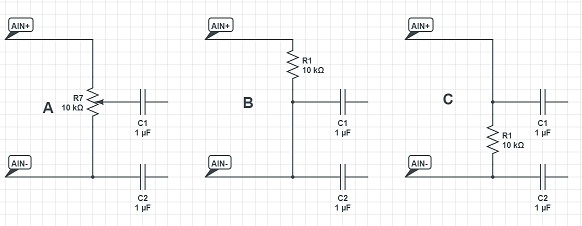 Best wishes, Tom Game*Mite, CMM2 Welcome Tape, Creaky old text adventures |
||||
| mozzie Regular Member Joined: 15/06/2020 Location: AustraliaPosts: 68 |
G'day, Not sure the audio gods are ever satisfied, hence my choice to generally ignore them, Audio Agnostic perhaps  @Thwill Driving the pwm straight into the PAM pushes it straight into clipping, even with any volume control pretty much shorting the inputs it will have enough gain for the common mode signal to overdrive it. This was the subject of some of the very early circuits before the Mono option in the Play Sound function. In regards to previous post. Should have mentioned C3/C6 are optional and as @Turbo46 suggests, dropping the value of C5/C8 will do similar but with a gentle roll off slope and less attenuation, play with values to see what works with your setup. The correct number of components is the minimum possible that performs to your satisfaction. The volume control issue using a single pot was as the volume of the "sound" is reduced, the clicks and pops etc stayed constant and at low volume settings they are quite pronounced, the dual pot setup reduces it all as the volume is reduced. Try it out at lower volumes with the single pot and if your happy with the results, happy days  Regards, Lyle. P.S. should I refer to users by there signature name or real name? or does it not matter? |
||||
| thwill Guru Joined: 16/09/2019 Location: United KingdomPosts: 3839 |
Thanks Lyle, I've not been hearing these (except the pop on startup which I may choose to live with even if it can be worked around by dedicating a GPIO line to the SD pin). Perhaps Peter's improvements to the firmware helped in this regard. I don't think it matters, certainly not to me. If I am addressing someone directly I will usually use their real name if I know it, and if I am referring to somebody in the third person I will usually use their @Handle. Context is everything. Best wishes, Tom Game*Mite, CMM2 Welcome Tape, Creaky old text adventures |
||||
| Turbo46 Guru Joined: 24/12/2017 Location: AustraliaPosts: 1593 |
Hi Tom, What Mozzie said. First you need to understand that the amplifier is a DIFFERENTIAL amplifier. It amplifies the difference between the two inputs. The two 68k resistors are a necessary part of the circuit and define the gain. 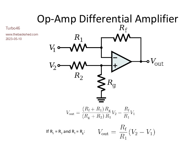 Without them, the on board 100 ohm resistors are setting the gain, so it will be very high and you will be over driving the amp so it will be just feeding the speaker with a digital ON/OFF signal which the speakers are effectively 'filtering' because they can only produce a range of frequencies. The two filtered PWM outputs should be equal and opposite. With the 68k resistors in circuit and with a pot connected between the IN+ and - inputs consider when the pot is set at zero resistance. The DIFFERENCE between the + and - input is zero so the output is zero or there about depending on the matching of the components. When the pot is at maximum, the DIFFERENCE between the + and - inputs will be at the maximum and so will the volume or gain. In one of your circuit's configurations you are actually connecting two Pico outputs together via capacitors. That may produce some high current spikes in the outputs and damage the micro. I hope that clears it a little Bill Keep safe. Live long and prosper. |
||||
| Mixtel90 Guru Joined: 05/10/2019 Location: United KingdomPosts: 5725 |
Unfortunately the data sheet for the PAM8302A tells lies. It shows a diagram on page 2 which suggests that the input is differential but later it describes the same dual op-amp arrangement as the LM4871. If it can contain a severe screw-up like that then there's no reason to trust much more of it. :) From the PAM8302A: As shown in block diagram (Page 2), the PAM8302A has two internal amplifier stages. The first stage's gain is externally con figurable, while the second stage's is internally fixed. The closedloop gain of the first stage is set by selecting the ratio of RF to RI while the second stage's gain is fixed at 2x.The output of amplifier one serves as the input to amplifier two, thus the two amplifiers produce signals identical in magnitude, but different in phase by 180°. Consequently, the differential gain for the IC is A =20*log [2*(RF/RI)] From the LM4871: As shown in Figure 3, the LM4871 has two operational amplifiers internally, allowing for a few different amplifier configurations. The first amplifier's gain is externally configurable; the second amplifier is internally fixed in a unity-gain, inverting configuration. The closed-loop gain of the first amplifier is set by selecting the ratio of Rf to Ri while the second amplifier's gain is fixed by the two internal 40kΩ resistors. Figure 3 shows that the output of amplifier one serves as the input to amplifier two, which results in both amplifiers producing signals identical in magnitude, but 180° out of phase. Consequently, the differential gain for the IC is AVD= 2 *(Rf/Ri) (1) I might be tempted to put high value resistors to ground after the input capacitors to let them charge. Several hundred k. In a true op-amp it won't make any difference to the output voltage as both inputs are still at the same voltage. Mick Zilog Inside! nascom.info for Nascom & Gemini Preliminary MMBasic docs & my PCB designs |
||||
| thwill Guru Joined: 16/09/2019 Location: United KingdomPosts: 3839 |
Subject to local labour laws every Bintendo Tomboy will come with a small child and a yellow plastic trumpet to provide music and sound FX. Best wishes, Tom Game*Mite, CMM2 Welcome Tape, Creaky old text adventures |
||||
| Mixtel90 Guru Joined: 05/10/2019 Location: United KingdomPosts: 5725 |
Now *that's* what I call "sound thinking"! Mick Zilog Inside! nascom.info for Nascom & Gemini Preliminary MMBasic docs & my PCB designs |
||||
| mozzie Regular Member Joined: 15/06/2020 Location: AustraliaPosts: 68 |
G'day Tom, You may have just found the solution to the Bintendo Audio Conundrum  This will definitely cause anger and gnashing of teeth with the gods of audio fidelity....  By cutting the track (top right) shown in the photo and disabling the on board volume control, the gain of the PAM8302 can be reduced to a suitable level to allow the PWM signal to stay under control, the "Volume Control" now controls the amplitude of the PWM. 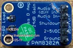 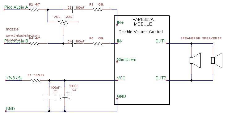 It works, not hifi and a little noise is back but for your application it might be all that's required. Component values will need finessing to adjust gain / volume. Regards, Lyle. |
||||
| thwill Guru Joined: 16/09/2019 Location: United KingdomPosts: 3839 |
Ay up Lyle, You mean the child and the trumpet? ... they'd have to be very small . Right so the track you are suggesting cutting is the one connecting AIN- to the internal pot ? You would then set the internal pot to provide 0R between AIN+ and the internal (C1) 1uF. Then you are controlling the volume with an external pot across the PWM inputs like I was trying but failing. I'll give it a go when I order some more PAM8302s. In the meantime I've actually soldered your previous approach, but with a 50K variable resistor across the inputs to the module, to the mk2 prototype. 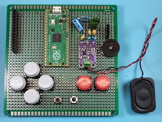 * Note I know I've forgotten the "voodoo" 2R2 on the power supply, not intentionally. Seems to work, but the b***dy thing may have been "ticking" again until I ramped up the CPU, the problem now is that I'm "ear blind" to "The Entertainer". When @bigmik lays out the PCB I'm going to ask for him to allow for a lot of flexibility (a header so it can be taken "off board" and spare plated holes) in the audio section so that if anyone does build one they can have as much *fun* as I am  . .Best wishes, Tom Edited 2023-05-11 02:27 by thwill Game*Mite, CMM2 Welcome Tape, Creaky old text adventures |
||||
| Turbo46 Guru Joined: 24/12/2017 Location: AustraliaPosts: 1593 |
Tom and Mozzie, If there is sufficient gain with the circuit as is then I don't see the point of cutting out the internal pot. Not having a module I don't actually know which track you are cutting. Regarding the 2R2 resistor in the supply. You really need that to decouple the amp supply from the main supply. Without it the 100u and 100n capacitors are trying in vain to filter the whole power supply. This is probably why the ticking has returned. Bill EDIT: I still think it is worthwhile setting the SD input low when no sound is being played. It's only one wire and little overhead in the program and would extend battery life. It may only save 3 to 5mA but that may be more as it seems there is always a bit of noise going through the amplifier. Edited 2023-05-11 11:40 by Turbo46 Keep safe. Live long and prosper. |
||||
| thwill Guru Joined: 16/09/2019 Location: United KingdomPosts: 3839 |
I think the blue track: 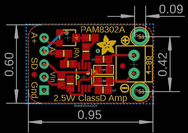 I'm not certain but I think it's possible @Mozzie's latest proposal also included removing the low pass filter ... perhaps an omission, or perhaps relying on the capacitors and ferrite beads on back-end of the module and the speaker itself to do a good enough job (?) In any case I have committed the earlier PAM8302 design to protoboard for the Mk2 now. Ack, it was an accidental omission, and also omitted on my breadboard - which wasn't ticking - it may well be in my head - I'll worry about it later if it's still there once the whole prototype is built. OK, I will take a look. Best wishes, Tom Game*Mite, CMM2 Welcome Tape, Creaky old text adventures |
||||
| mozzie Regular Member Joined: 15/06/2020 Location: AustraliaPosts: 68 |
G'day, Perhaps a noisy cricket might be suitable for fitment into the Tomboy, you get noise and haptic feedback in one package (6 legs) and less headaches than a small boy + trumpet... Tom mentioned he fed the PWM from the Picomite straight into the PAM amp, this just expands on that idea... Cutting the track (yes the blue one) disables the on board volume control and allows us to set the gain for the PAM8302 using external resistors (R3/R5), if we do this and bring the gain down so that the amp is still high frequency modulating the lower frequency PWM from the Picomite we don't need a filter, the speaker will do it for us. If we now use the external volume control to adjust the amplitude of the PWM going into the PAM amp, it will adjust its modulation to suit, and we have audio from the speaker with very few external components, possibly the lowest realistic component count, even C3 and C4 are optional due to the 1uF caps on the PAM module. This works surprisingly well here with my setup, not hifi but it could be ok for the Tomboy application. I still recommend the earlier circuit with filters etc and stereo volume control as a better solution. The idea of putting the audio circuit on a sub-board is a good one, allows tinkering with the design, then the "fun" can continue even after the main board design has been finalized...  Can I suggest once again if you haven't already tried and you have a spare analog input, wire the volume control to it and do the volume control in software, then the circuit is possibly R1 + C1 + C2 + R3 + R5 and thats it... Regards, Lyle. |
||||
| thwill Guru Joined: 16/09/2019 Location: United KingdomPosts: 3839 |
How do Lyle, The Mk2 prototype has an in-between design as previously indicated, I'll post a schematic of the whole thing once I finish soldering it up over the weekend. For the PCB, assuming there is room, I will ask @bigmik to put the footprint for your full solution as it's easy enough to build the simpler ones upon that and either not connect or bridge some of the connections as appropriate. I'm not enthused by this (or even really @Turbo46's suggestion of putting the module's disable pin under software control). I think it adds unnecessary burden on the software author, i.e. every program will then need to monitor that analog input. HOWEVER I have rejigged the pin allocation so it will be possible to wire it up like this in the future. Best wishes, Tom Edited 2023-05-12 20:00 by thwill Game*Mite, CMM2 Welcome Tape, Creaky old text adventures |
||||
| mozzie Regular Member Joined: 15/06/2020 Location: AustraliaPosts: 68 |
G'day Tom, Makes perfect sense now you point it out, that if others are writing games for the Tomboy any extra software overheads are just a burden  Hopefully the original circuit with a bit of tweaking does the job and crickets / small boys and trumpets are not required. Regards, Lyle. |
||||
| thwill Guru Joined: 16/09/2019 Location: United KingdomPosts: 3839 |
Note that I'm not delusional enough to think anyone other than I will be writing (or porting) games for the Tomboy*, and even I will be making sure anything I do will be transpileable to run on the CMM2 and PicoMite VGA as well. Best wishes, Tom * Or even playing them, though I hope my daughters might get some entertainment from it (or at least humour their dad) on long car journeys and it will hold off the siren's call of the mobile phone for a couple of years. Edited 2023-05-12 20:36 by thwill Game*Mite, CMM2 Welcome Tape, Creaky old text adventures |
||||
| JohnS Guru Joined: 18/11/2011 Location: United KingdomPosts: 3656 |
Hahahahahaha Yeah, right. John |
||||
| Volhout Guru Joined: 05/03/2018 Location: NetherlandsPosts: 3521 |
Volume control in the digital domain goes at the cost of resolution. If you want to have the audio level 8 times softer, you loose 3 bits in resolution. Since the human ear works logaritmic, 8 times is not all that much difference in loudness. But the loss in resolution will effect the audio quality a lot. The PWM output is near 11 bits resolution. The MP4822 DAC is 12 bits. It can be done, but may disappoint you. Everything may start sounding like crickets... Volhout PicomiteVGA PETSCII ROBOTS |
||||
| Turbo46 Guru Joined: 24/12/2017 Location: AustraliaPosts: 1593 |
Good luck with that. A tablet might do it. I'm glad that you are starting the second (hopefully final) prototype. To be honest, I would have pursued the suggestion by Volhout and used diode clipping to try to remove the noise. To me that has the most potential. Clipping the PWM signal when it is at a logic one should remove the noise from the signal caused by the power supply. With the straight PWM signal, the noise from the power supply will be on the signal when it is a a logic one but when it is at logic zero, there should be no noise (or very, very little). Using a differential input amplifier Should remove the noise when it is the same level on both inputs. But, the noise is not at the same level on both inputs all of the time. Because the two PWM signals are producing Their own version of the audio signal and the two audio signals are 180 degrees out of phase the two cannot always be at logic one at the same time. There MUST be times when one is at logic one while the other is at logic zero. At those times there will be noise on the one side of the differential amplifier and not on the other so it will be amplified and fed to the speaker. The noise level should be improved but I believe that the diode clipping should produce a lower noise level on the audio signal. The analogue gods are fickle and sometimes are not easy to please. Bill Keep safe. Live long and prosper. |
||||
| thwill Guru Joined: 16/09/2019 Location: United KingdomPosts: 3839 |
Hi folks, Does anyone have any comment on the effect of driving the PAM8302 mono-amplifier from a stereo signal, Left => AIN+, Right => AIN- I've done this accidentally and it (surprisingly?) seems to work, and it would be convenient if this were a "harmless" thing to do. Note that I am not looking at a way of mixing Left & Right into a mono signal (I've seen suggestions on how to do that on the internet), I'm just enquiring as to whether what I've accidentally done is ultimately going to fry the PAM8302. EDIT: the reason I'm keen to know is that whilst I've built the Bintendo Tomboy to expect a mono sound signal (PLAY SOUND with MONO flag), someone is sure to feed it a stereo signal from PLAY TONE or PLAY WAV at some point. Best wishes, Tom Edited 2023-06-04 00:31 by thwill Game*Mite, CMM2 Welcome Tape, Creaky old text adventures |
||||
