
|
|
Forum Index : Electronics : Nanoverter and Backfeeding with a GTI
| Author | Message | ||||
| poida Guru Joined: 02/02/2017 Location: AustraliaPosts: 1389 |
Madness: I am pleased to see you found something that helps. It might be important to review the calculations that produce the PWM pulse width. With this code, I start with 50% duty for both V1 and V2 and soft start code then lets both outputs grow up to a point where Vfb = setpoint. I just tested u = 30000.0 * sin(t); and the soft start got to 240V and stabilised there in closed loop control. I have no idea why I left it at 20000.0, that only got my test inverter up to 199V AC It's important the calculations do not overflow or underflow or produce a TIMER1 duty width <= 0 or >= 800 Taking that value to 32,000 is guaranteed to be safe, the expression c = (l[pcount] * vpwr) >> 16; must never return a number close to or greater than 1/2 PPWM or 400 vpwr will range from 0.01 x 800 (or 8) to 0.99 x 800 (or 792) eg (32,000 x 792) = 23,760,000 then divide by 2^16 or 65536 and then is 362 We have about 35 more counts headroom before we get close to 400 Edited 2023-04-25 16:11 by poida wronger than a phone book full of wrong phone numbers |
||||
Madness Guru Joined: 08/10/2011 Location: AustraliaPosts: 2498 |
So I was on the right track then to correct the voltage? I have spent quite a bit of time working out what each line of the code is doing and adding comments to try to get up to speed with what the code is about. The small test rig ran most of the day nicely with nearly 1KW at times produced by the GTI. The single toroid and heatsink got to just over 30 degrees with no fans and an ambient temperature of around 25. I made up this AC current sensor setup to use as per the hack. 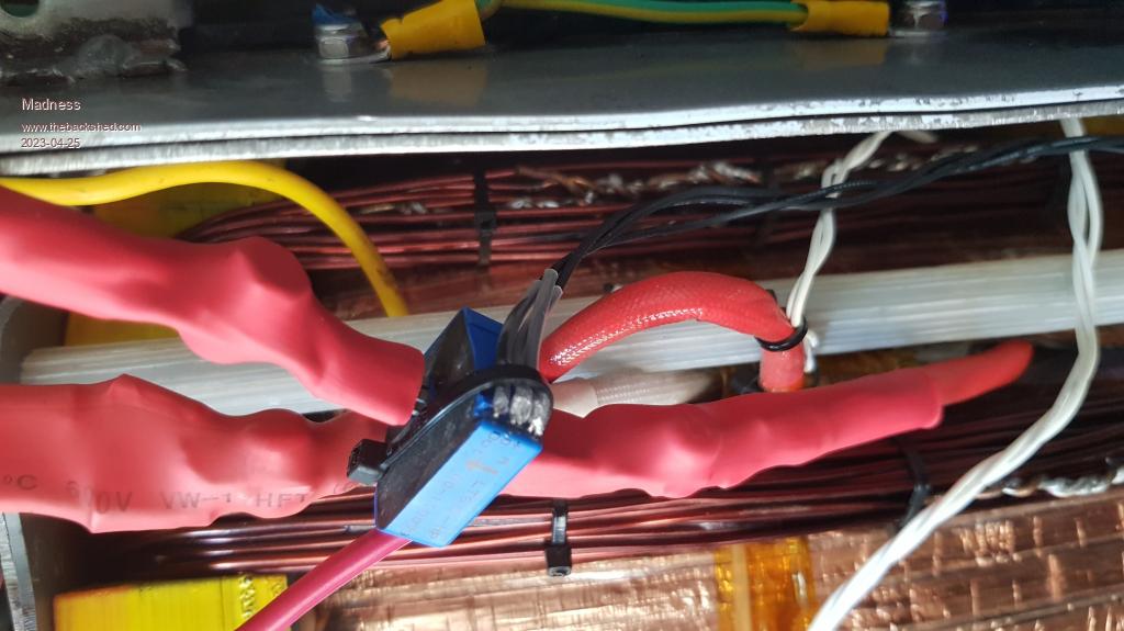 The Nanoverter control card is now fitted to my new inverter. But something is not right, I have no control over the AC voltage in this inverter, it sits on 232 and does not change. the waveform is slightly distorted just after the peak on the bottom side while the top is perfect. It was running perfectly with the Murphy version of Nano1 code, so I am thinking the changes you have just posted will sort that out. I will give that a try tomorrow, I have had enough playing with inverters for one day. Here is a new GTI regulator that I have made. 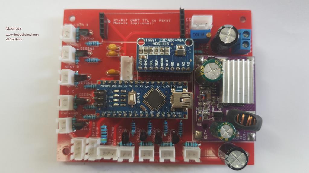 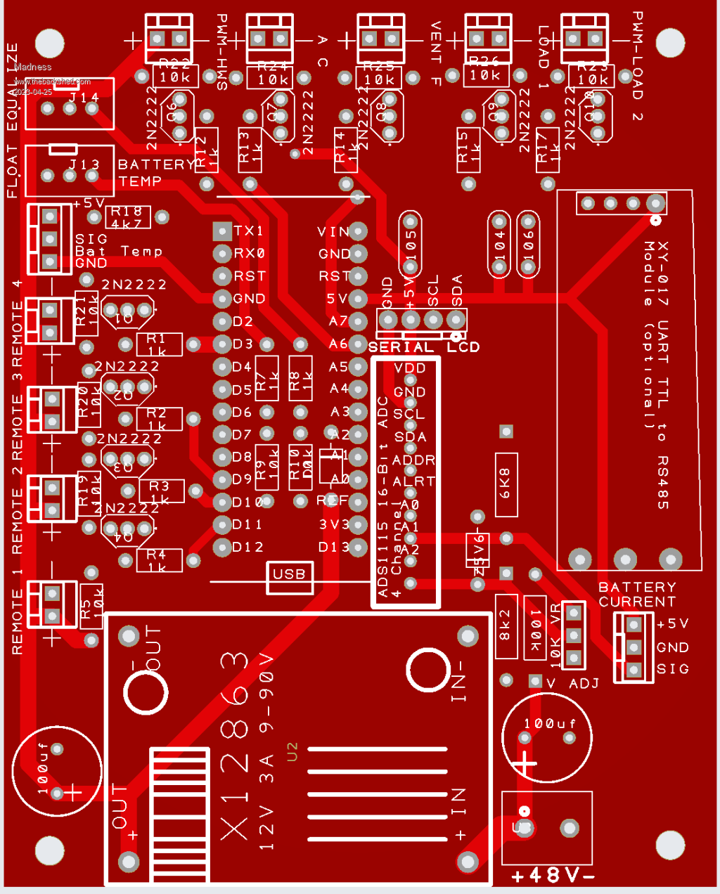 This does not have any MOSFETs on the master board, I have moved them to inside the GTI so the high voltage DC and AC all stay sealed up in the GTI. 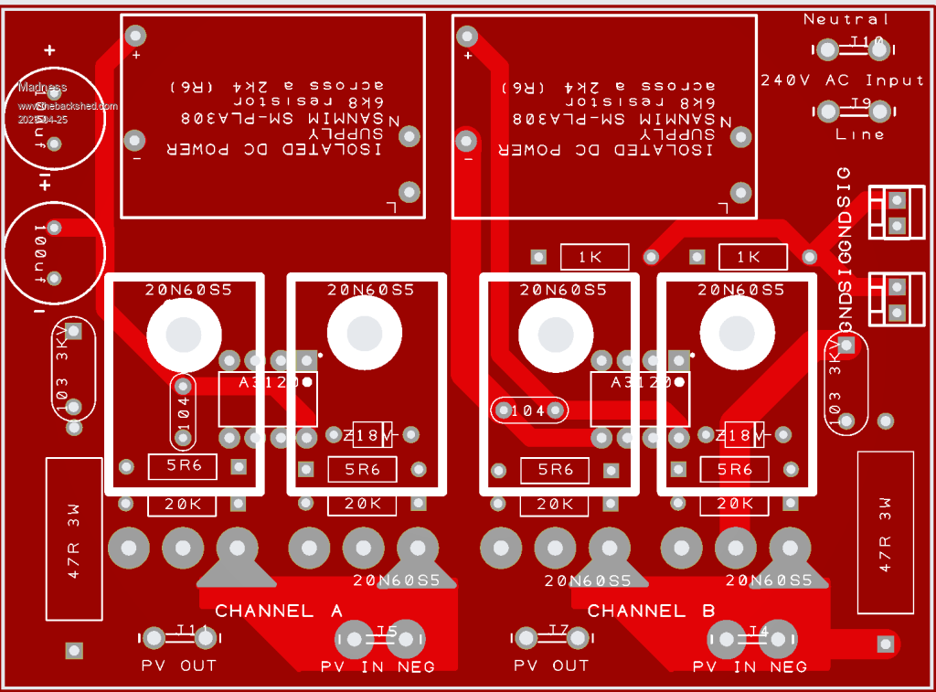 It just uses a 12V PWM signal from the master to each slave to regulate the DC input within the GTI. I have 3 GTI's running like this, there is a battery current sensor to keep the battery current under the limit I have set. It first turn on my hot water if the current is too high then if needed it will reduce the GTI DC input as well. Edited 2023-04-25 16:44 by Madness There are only 10 types of people in the world: those who understand binary, and those who don't. |
||||
| Madness Guru Joined: 08/10/2011 Location: AustraliaPosts: 2498 |
The head-scratching continues. After running so well on the small test rig, single Aerosharp core, 4 FETs in total I can't say the same about my new big inverter. This big inverter is 3 cores and with my big power board with its full 24 FETs. I was able to increase u = 30000.0 * sin(t); to 32000.0 in increments on the small test rig and the output voltage was correct and stable from 22000 right through to 32000. The big inverter is not the same, I could not alter the output voltage at all it went to 370VAC. The only way I could correct this was to reduce u to 24000, then I could adjust the voltage and set it to 230V. It also has this small kink in the waveform.Due to my phone camera's shutter speed, it missed capturing the full wave, the missing part looks identical to the bottom of the wave to the right. 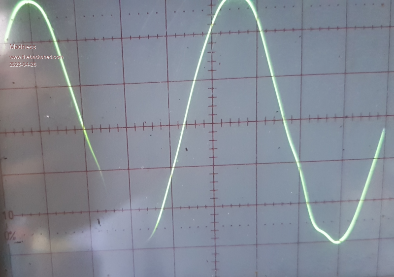 The GTI refused to connect with this sub-standard sine-wave. This same inverter runs perfectly with the Murphy version of the Nano1 code, voltage regulation works as it should and the sine-wave is perfect, the only problem is I can't connect a GTI. Edited 2023-04-26 10:40 by Madness There are only 10 types of people in the world: those who understand binary, and those who don't. |
||||
| InPhase Senior Member Joined: 15/12/2020 Location: United StatesPosts: 178 |
Besides the number of FETs and the transformer itself, what is different between the test rig and the big inverter? |
||||
| Madness Guru Joined: 08/10/2011 Location: AustraliaPosts: 2498 |
Both have 2 chokes, the test rig has 2 pairs of small Aerosharp cores with 7 turns and about 40 microhenries. The big inverter has 2 large aerosharp cores with 12 turns and 80 microhenries. The same Nanoverter control board is used in both. As I mentioned above this big inverter runs perfectly with the different Nano1 code, so I don't believe it is a hardware issue. The modulation is different, one is Bipolar the other is Unipolar, the Bipolar code is an old version of the code and may have other issues in the code. There are only 10 types of people in the world: those who understand binary, and those who don't. |
||||
| InPhase Senior Member Joined: 15/12/2020 Location: United StatesPosts: 178 |
So the 2x Sine code on the test rig runs well and the GTI connects, but the 2 x Sine code on the big inverter has this hiccup in the waveform? |
||||
| Madness Guru Joined: 08/10/2011 Location: AustraliaPosts: 2498 |
Yes, but the sinewave is fine with the Murphy version of the code. I think I detailed all this above. The 2 different types of modulation are detailed in this video https://www.youtube.com/watch?v=vOtamo-Vpvw Edited 2023-04-26 12:14 by Madness There are only 10 types of people in the world: those who understand binary, and those who don't. |
||||
| nickskethisniks Guru Joined: 17/10/2017 Location: BelgiumPosts: 416 |
A few ideas you can try? If your output voltage went to 370Vac, you might have some headroom to add a(few?) extra primary windings. I didn't test it but I have this idea this gives less deadtime and so nicer sinewave. An emi filter between inverter and GTI? Playing with the primary series inductor value? Maybe a little series resistor between inverter and GTI? It may not be the waveform that's the problem, the grid can be much worse I guess, it might be the impedance of your inverter? Maybe you can monitor the current and phase shift between the current and voltage. Edited 2023-04-26 16:05 by nickskethisniks |
||||
| Madness Guru Joined: 08/10/2011 Location: AustraliaPosts: 2498 |
VFB issue was in the connector I had made up that plugs into the PCB, fixed that and the voltage regulation actually works now. This is with the Murphy code version and the 2Xsine with variable u set to 32000. Changing between the 2 code versions gave the same output voltage with no other changes. At least the inverter can survive 370VAC and has plenty of headroom there for big loads. Still have the same sine-wave as shown above with the little kink. Just got this working but can't connect the GTI as there is not enough sun, so I will have to wait until tomorrow to test it. There are only 10 types of people in the world: those who understand binary, and those who don't. |
||||
| rogerdw Guru Joined: 22/10/2019 Location: AustraliaPosts: 803 |
I may have missed it ... but what type of GTI are you using ... is it a LF inverter with a toroid tx ... or HF inverter? Cheers, Roger |
||||
| Madness Guru Joined: 08/10/2011 Location: AustraliaPosts: 2498 |
I have 3 ABB Aorura 5KW GTIs that are in use every day. They are HF type been running this setup with an EG8010 driven inverter for the last 7 years. But I would like the ability to sync with a generator which is why I am working on getting this new inverter to work with the Nanoverter code. First I need to get the back feeding working then I can start working on the generator sync. There are only 10 types of people in the world: those who understand binary, and those who don't. |
||||
| mab1 Senior Member Joined: 10/02/2015 Location: United KingdomPosts: 164 |
+1 for Nicks point about waveform not being an issue for gtis. Even with the washing machines triac speed controller crinkling up the waveform on my powerjack, the gtis lock in without issue. If it were me I'd go back to basics and double check the a.c. without assumption; as if you were coming to diagnose this issue on someone elses inverter. I.e. frequency, voltage, stability , L/N polarity (come to think of it i don't know if gtis care about polarity or if they accept floating, unpolarised a.c.). I assume the gtis are not giving any clue as to why they aren't connecting? |
||||
| Madness Guru Joined: 08/10/2011 Location: AustraliaPosts: 2498 |
There are some cheap Chinese GTI's that probably don't care what they are connected to. The GTIs I am using are quite advanced in detecting the state of the AC grid as these have to meet the local grid power regulations. I can connect a computer to the ABB GTIs with RS485 and there is a very extensive range of options. These include getting into service mode and being able to change a lot of settings that I do not know what effect many of them would have. However there should be no need to tweak the GTI, they should just connect straight out of the box. They do work now and have done for a long time with no issue at all with the EG8010 inverter that is running my house now. The EG8010 inverter and the powerjack use a different modulation technique to the Nanoverter this diagram from https://www.thebackshed.com/forum/ViewTopic.php?TID=9409&PID=135605#135605#135605 by Poida shows what it looks like. 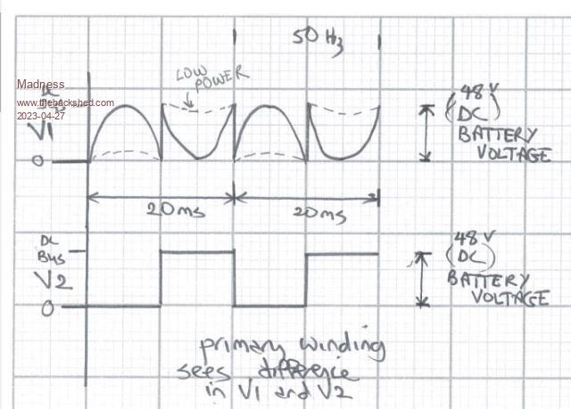 This is the modulation that I am working with here. 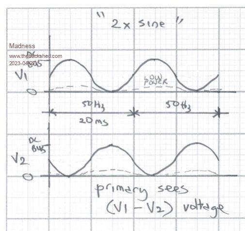 And this is the modulation used in the current Nanoverter code. While this modulation works very well for an inverter that is only providing AC power it is not good with backfeeding from a GTI and I think it would also not work with a generator. 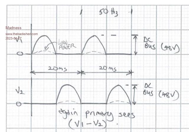 If all goes to plan I will be making new PCBs designs for all to download that will connect to a generator second inverter, sync with it, charge batteries and or run bigger loads. This will need to be plug and play apart from a few settings for current limit etc. There are only 10 types of people in the world: those who understand binary, and those who don't. |
||||
| mab1 Senior Member Joined: 10/02/2015 Location: United KingdomPosts: 164 |
Hmm. Well the three gtis I'm using with my powerjack are all SMA sunny boys - neither cheap nor Chinese i don't think, and they have to meet the uk grid spec. They can be programmed for off grid ( i think clockmanfr does that with his), to make them less sensitive to the kind of glitches you get when running off an inverter instead of the grid, but mine are still set for uk grid tolerances, and only disconnect if I'm using the MIG welder on max power or starting the lathe. I still don't understand why the modulation method would make a difference TBH, as long as the 230v out is approximately sinusoidal, so I'll be very interested to see how this pans out. It's good to know the eg8010 based inverters back feed ok though, as that's what I've got as a backup if the PJ ever fails. Good luck. |
||||
| Madness Guru Joined: 08/10/2011 Location: AustraliaPosts: 2498 |
The modulation method does make a difference, the only person I am aware of that has a GTI working but not properly with standard Nanoverter code is Murphys friend. A GTI will connect no problem using the standard Nanoverter code as long as there is more power being used than what the GTI is producing. In other words, it will not backfeed, to backfeed the inverter needs to act as a rectifier and a boost converter. The Primary windings in our inverter transformers are set up to work at a voltage much lower than the battery voltage. This is so that as our AC loads increase the primary voltage can increase to maintain a constant AC output voltage. What I believe is happening is that the unipolar modulation shown in the bottom diagram above is only connecting battery positive on one half of the sine wave and then only battery negative on the other half of the sine wave. Bipolar modulation connects both positive and negative at the same time, this is similar but not quite the same as the EG8010 modulation. If you watch the video I have linked above it goes into a lot of detail about the 2 types of modulation. So why not just use the EG8010? That is because we can not sync the EG8010 with a generator and this is why I am experimenting to find a way that I can sync a generator and back charge with it. Another possibility is getting the Nanoverter to use the same modulation as the EG8010 but I don't have code for that at present. There are only 10 types of people in the world: those who understand binary, and those who don't. |
||||
| noneyabussiness Guru Joined: 31/07/2017 Location: AustraliaPosts: 506 |
just an idea, maybe connect a beefy bridge rectifier to the output of your generator, then feed the subsequent dc into a gti ... not quite as efficient as other methods, but it would be up there ... and the genny would be supporting the load as well.. I think it works !! |
||||
| poida Guru Joined: 02/02/2017 Location: AustraliaPosts: 1389 |
I would rather an active rectifier that uses FETs for the bridge rec. They can be built with tiny power loss. NXP device wronger than a phone book full of wrong phone numbers |
||||
| Madness Guru Joined: 08/10/2011 Location: AustraliaPosts: 2498 |
That will work but a big drawback is that the rectifier is only going to take the peaks of the generator's AC sine wave. Edit: Or do as Poida said, still there will be losses from a GTI. Although there will be losses back feeding back into batteries as well. Whatever way you do it it's not perfect, or could one of those NXP devices output battery voltage from 240VAC? Edited 2023-04-27 10:27 by Madness There are only 10 types of people in the world: those who understand binary, and those who don't. |
||||
| poida Guru Joined: 02/02/2017 Location: AustraliaPosts: 1389 |
Madness: just a detail on the 2x Sine modulation that needs to be cleared up. In the above diagram I show incorrect "low power" voltage traces. The incorrect trace has them close to zero DC volts. The CORRECT trace should have the voltages close to 1/2 DC supply volts with the small amplitude 50Hz deviating from that mid point location. It results in the same voltage difference (V1 - V2) With zero modulation amplitude, that is, at the start of the soft start or the end of the soft stop, both V1 and V2 will be 1/2 DC Volts. I just wanted to correct that error now, since it looks like more interest in the 2x Sine modulation is happening. wronger than a phone book full of wrong phone numbers |
||||
| Madness Guru Joined: 08/10/2011 Location: AustraliaPosts: 2498 |
Thanks Poida, have you watched this video? https://www.youtube.com/watch?v=vOtamo-Vpvw You could just jump through quickly to see the different types of modulation, I would be interested in know if the Bipolar version is identical to your 2X Sine. There is a lot of other very good videos on that channel that are relevant also. There are only 10 types of people in the world: those who understand binary, and those who don't. |
||||
