Notice. New forum software under development. It's going to miss a few functions and look a bit ugly for a while, but I'm working on it full time now as the old forum was too unstable. Couple days, all good. If you notice any issues, please contact me.
analog8484 Regular Member Joined: 11/11/2021 Location: United StatesPosts: 92
Posted: 04:52pm 30 Apr 2023
Copy link to clipboard
Print this post
I should have clarified that I meant the "2xSine" nanoverter modulation is unipolar where the each half bridge is driven by a different sine wave. Edited 2023-05-01 02:54 by analog8484
analog8484 Regular Member Joined: 11/11/2021 Location: United StatesPosts: 92
Posted: 05:04pm 30 Apr 2023
Copy link to clipboard
Print this post
Nice. Looks quite hefty. The OGI power capacity looks similar to the one KeepIS build recently. So, it might good for up to 10kW. The 120A (~5-6kW) max backfeed current is well under the 1:1 ratio for OGI and 0.5C of the 37.kWH battery bank. I guess you must have a lot of loads and/or your 3x5kW GTI's only produce a fraction of their capacity (15kW).
analog8484 Regular Member Joined: 11/11/2021 Location: United StatesPosts: 92
Posted: 05:12pm 30 Apr 2023
Copy link to clipboard
Print this post
I suspect the standard nanoverter may also work better now with choke fix.
analog8484 Regular Member Joined: 11/11/2021 Location: United StatesPosts: 92
Posted: 05:21pm 30 Apr 2023
Copy link to clipboard
Print this post
I wonder if a lower inductance choke could be used is due to the use of 2xSine (unipolar) PWM modulation. One advantage of unipolar PWM modulation is the shift of PWM switching spectrum to higher frequencies that allows the use of smaller/lighter magnetics. Edited 2023-05-01 03:28 by analog8484
Madness Guru Joined: 08/10/2011 Location: AustraliaPosts: 2498
Posted: 07:47pm 30 Apr 2023
Copy link to clipboard
Print this post
The small test inverter proved that the 2 X SINE is the only one that works, it had smaller chokes all along. Apart from that the only person I am aware of that could use the Nanoverter in any way with back feeding is Murphy's friend. He has said here that it still makes noises and the waveform is not so good. It will work as long as there is no back feed, but once it starts to back feed it goes pear-shaped very quickly. Not being able to back feed is an issue Poida is aware of.
The post with the photo you quoted above is actually the old inverter that I have been using the last 6.5 years.There are only 10 types of people in the world: those who understand binary, and those who don't.
Madness Guru Joined: 08/10/2011 Location: AustraliaPosts: 2498
Posted: 08:07pm 30 Apr 2023
Copy link to clipboard
Print this post
The standard nanoverter appears to run perfectly with the larger chokes. It was only when trying to back feed that the choke size became an issue. I have not tried changing to the standard nanoverter modulation since changing the chokes.
The post with the photo you quoted above is actually the old inverter that I have been using the last 6.5 years. Edited 2023-05-01 06:22 by MadnessThere are only 10 types of people in the world: those who understand binary, and those who don't.
Madness Guru Joined: 08/10/2011 Location: AustraliaPosts: 2498
Posted: 08:23pm 30 Apr 2023
Copy link to clipboard
Print this post
So much for that, connected the inverter to the house it ran for about 5 minutes and now the MOSFETs are blown to pieces.
I am taking a break from this for a little while. Edited 2023-05-01 21:27 by MadnessThere are only 10 types of people in the world: those who understand binary, and those who don't.
Madness Guru Joined: 08/10/2011 Location: AustraliaPosts: 2498
Posted: 11:32am 01 May 2023
Copy link to clipboard
Print this post
This is the first MOSFET failure I have had with the nanoverter card. Startups are normally so undramatic with the nice soft start and soft shutdowns.
After thinking about this further I remembered when I first started the inverter this morning that on the first attempt starting it and I turned on one circuit the SCR over current was tripped. I had not set the pot for this so it was probably set too low. On the EG8010 PCBs if overcurrent is tripped and reset the inverter will soft start. That did not happen it did a hard start that sounded quite brutal, it must have jolted the toroid as there was a very loud thump, I wonder how many thousand amps passed through the MOSFETs in those initial milliseconds. I was not expecting this behaviour, it all happened in a few milliseconds and the inverter was running. I had a switch on the SCR circuit as I did not have a suitable normally closed momentary push button switch. However, the correct switch would have still resulted in a hard start. So as the inverter was running I thought everything was fine but was it, chances are very high there was damage as a result of this causing the failure a few minutes later.
The power board is beyond repair, all 24 MOSFETs are blown and several of the totem pole transistors are burnt as well as quite a few resistors, PCB tracks and the PCB is burnt right through in one spot. I have not tested the nanoverter PCB yet but I doubt the MOSFET drivers survived going on past experience when a failure goes past the totem pole transistors.
I know some don't see value in having the SCR overcurrent shut down, is the software-driven shut down as fast? The scr shutdown has saved me before with an oven that blew an element a few times. The first time was before I had the SCR shut down and it killed the inverter, the same fault in the oven occurred twice after that when I had SCR shut down. They shut down tripped and no damage was done. We have since replaced that oven due to these problems.
Anyway, I will use a new power board with just 4 MOSFETs and test the inverter with the chokes and everything else as it was when the failure occurred. I think that there is a very high probability that the hard start was the issue. In the meantime, I will leave the SCR shutdown disabled until I can sort out the hard start issue.There are only 10 types of people in the world: those who understand binary, and those who don't.
Murphy's friend Guru Joined: 04/10/2019 Location: AustraliaPosts: 600
Posted: 03:15pm 01 May 2023
Copy link to clipboard
Print this post
You are not the only one blowing mosfets .
As you know, I have several inverters and am often experimenting with them. I did a really stupid thing to my small (1.5KW) inverter. I had the light circuit for the house running on street grid while I had disconnected that small inverter which usually powers the lights. Somehow I managed to start it while it was still connected to street grid . Since these inverters do not grid synchronise, the result was spectacular.
There were 12 Mosfets, all blown.
As they are on 4 small carrier boards, there was no damage at all to the driver & power board. Not even soot, the carrier boards took the brunt of the damage.
So my meccano style build paid off, as did the opto isolated drivers. I think that idea makes it bullet proof, any Mosfet damage results in just swapping the cooked carrier boards for new ones.
Maybe something to consider if you are thinking about a new board design.
InPhase Senior Member Joined: 15/12/2020 Location: United StatesPosts: 178
Posted: 03:22pm 01 May 2023
Copy link to clipboard
Print this post
You could use a common household two-way light switch to prevent that in the future. Or any SPDT switch. The common would go to the house circuit, and the other two connections would be grid and inverter. It would be impossible to put grid and inverter together.
analog8484 Regular Member Joined: 11/11/2021 Location: United StatesPosts: 92
Posted: 04:31pm 01 May 2023
Copy link to clipboard
Print this post
Good point. I can see the standard nanoverter not working nearly as well for backfeeding since only the upper FET's in one half bridge are turned on per half line cycle.
Yes, I was wanting to better understand what you had working well for nearly 7 years.
analog8484 Regular Member Joined: 11/11/2021 Location: United StatesPosts: 92
Posted: 04:36pm 01 May 2023
Copy link to clipboard
Print this post
That's a bummer. Any idea what house loads were running? Is the SCR in addition to a circuit breaker feeding the house loads?
Madness Guru Joined: 08/10/2011 Location: AustraliaPosts: 2498
Posted: 08:38pm 01 May 2023
Copy link to clipboard
Print this post
I fitted a larger DC Breaker, if I had stuck with what I have in my other inverter the MOSFETs would blow and the damage would stop there.
These Transfer Switches are cheap and prevent connecting two power sources. I have been using the same brand for at least 6 years. There are only 10 types of people in the world: those who understand binary, and those who don't.
Madness Guru Joined: 08/10/2011 Location: AustraliaPosts: 2498
Posted: 08:49pm 01 May 2023
Copy link to clipboard
Print this post
The house load at the time was around 700W.
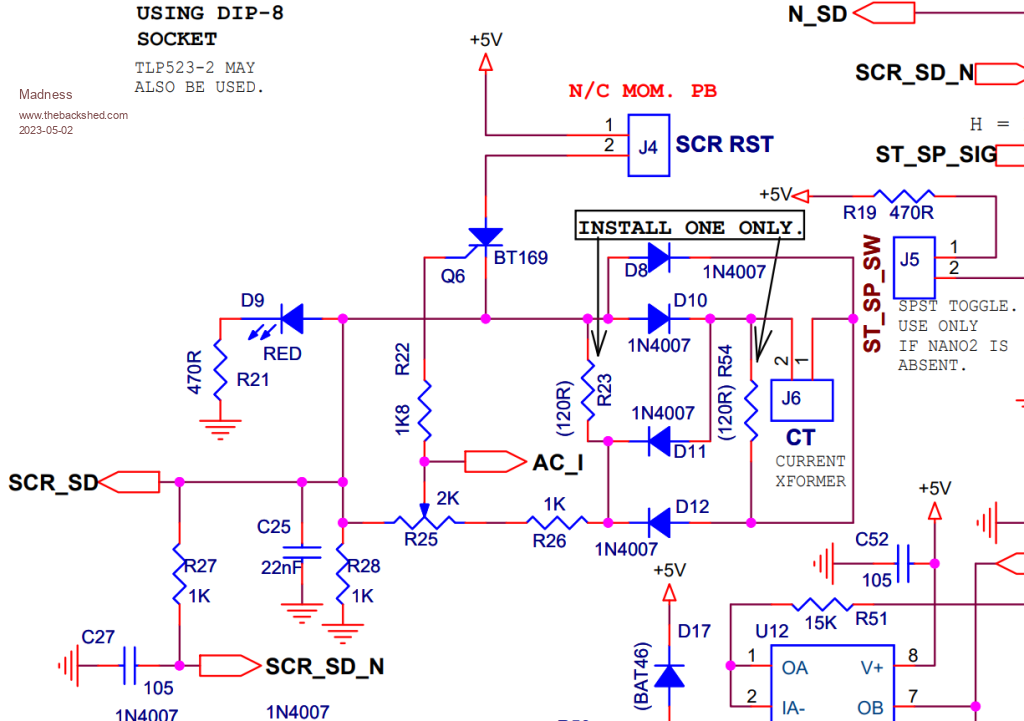
The SCR shutdown is part of the Nanverter control PCB, there is a 2000 turn current transformer on the AC output of the inverter. This circuit is connected to the Shut Down pins of the MOSFET driver ICs. If the AC current rises too far the SCR turns on the shutdown and the ICs turn off the MOSFETs instantly. It was the resetting of this and not expecting that the MOSFET drive signals to the driver ICs was still present that caused the hard restart, an not do a soft gradual startup as I was expecting.
There are only 10 types of people in the world: those who understand binary, and those who don't.
analog8484 Regular Member Joined: 11/11/2021 Location: United StatesPosts: 92
Posted: 04:00pm 02 May 2023
Copy link to clipboard
Print this post
Thanks for the clarification. Looking at the nanoverter code, it appears to not monitor the SCR shutdown input at all much less doing any protective PWM shutdown. No wonder the FET's blew. Edited 2023-05-03 02:15 by analog8484
Madness Guru Joined: 08/10/2011 Location: AustraliaPosts: 2498
Posted: 07:58pm 02 May 2023
Copy link to clipboard
Print this post
I have not looked at the code as yet but I am not surprised with what you found. Now that I am aware of it, all I need to do is flick the switch to stop the SPWM output and then reset the current trip if it triggers. The time I have had available has been spent on assembling a new power PCB. All going well I will have it running today with just a few MOSFETs for testing. Also, I will see if the cable I have used for the chokes can be forced into another turn around the core.
Once I get the back feeding working reliably then my next step is to start working on getting the nanoverter to sync with a generator and backfeed. That will require current sensing on the generator input and modifying the code to regulate the current load on the generator by reducing the inverters voltage. This will require a lot more protective disconnect/shut down functions in the code. Edited 2023-05-03 05:59 by MadnessThere are only 10 types of people in the world: those who understand binary, and those who don't.
Murphy's friend Guru Joined: 04/10/2019 Location: AustraliaPosts: 600
Posted: 09:07am 03 May 2023
Copy link to clipboard
Print this post
Thanks for that switch link above, Gary. I did not know such a switch exists.
I have a 3 position rotary switch; Inverter - OFF - Grid. This works IF I remember to check it before connecting something. I like your switch though, have put it on my list of modifications .
Regarding Nano inverter shut down, I never quite understood the SCR method Poida uses.
Instead I'm using the old method Oztules came up with, modified so that overload & undervoltage turn off the nano's ON switch. This works for me.
Madness Guru Joined: 08/10/2011 Location: AustraliaPosts: 2498
Posted: 11:09am 03 May 2023
Copy link to clipboard
Print this post
Those transfer switches disconnect line and neutral, plus they are a breaker as well.
The Oztules SCR shutdown pulled the current feedback pin high on the EG8010, which shut down the SPWM as well as directly shutting down the driver IC's. So the when reset the EG8010 did a normal startup with soft start.
If you are running a standard Nanoverter PCB then Nano1's D6 pin is connected to the SCR shutdown circuit and the code you are using checks that pin every half cycle and stops if it is high. So there is no need to have it connected to the on/off switch, under voltage is in the code as well. That SCR part of the code is not in the early version that Poida wrote with the 2XSINE. Obviously, that is something that was added sometime later. I need to look more at the code, I was too busy just working on getting the back feeding working.
The Inverter is close to being repaired, I have the power board running with just 4 MOSFETs ATM. As I suspected the MOSFET drivers on the Nano PCB were shorted out, just replaced them and the Nano PCB is back in action. All going well I will be connecting a GTI to the inverter sometime tomorrow for more testing. Also, I added an extra turn to each choke so now they have 4 turns each.There are only 10 types of people in the world: those who understand binary, and those who don't.
Madness Guru Joined: 08/10/2011 Location: AustraliaPosts: 2498
Posted: 11:11am 03 May 2023
Copy link to clipboard
Print this post
Edited 2023-05-03 21:13 by MadnessThere are only 10 types of people in the world: those who understand binary, and those who don't.
Revlac Guru Joined: 31/12/2016 Location: AustraliaPosts: 964
Posted: 11:06am 04 May 2023
Copy link to clipboard
Print this post
I'm a Bit late to the party, Even with a very clean sinewave I would still chose to use filters on the output, mostly to help with all the crappy loads such as the angle grinder and the large 1000w electric drill, sometimes the brushes can start arcing wildly, don't want that affecting the inverter. Or I should get some new brushes and fix the power tools.
Hope your inverter will be up and running (trouble free) again soon.Cheers Aaron Off The Grid


 .
. . Since these inverters do not grid synchronise, the result was spectacular.