
|
|
Forum Index : Microcontroller and PC projects : Anyone know Assembler language?
| Author | Message | ||||
| Volhout Guru Joined: 05/03/2018 Location: NetherlandsPosts: 3555 |
Afaik this code does not use i2c device address 0x60. It i2c writes to 0x90. The system uses a TV tuner as input, and takes the rf output to put that through a logaritmic amplifier (ad8307) as some form of spectrum analyzer or signal detector. Lew, why do you make this so difficult. I admit I like puzzles like this, but it would be fair if you start out your thread with "i want to reverse engineer this design and this is the code I found on the web". Knowing the application helps forum members with analyzing what the code is supposed to do. Volhout P.s. I remember these tuner settings from an earlier thread About using a tv tuner for one specific frequency, that was in the lowest part of the high band, but was programmed in the mid band. And tuner pll settings needed adjustment according Edited 2023-05-20 22:14 by Volhout PicomiteVGA PETSCII ROBOTS |
||||
| IanRogers Senior Member Joined: 09/12/2022 Location: United KingdomPosts: 151 |
CALL I2CSTART MOVLW 0xC0 ; Address CALL I2CBYTE That is 0x6 (in 7 bit address) and there is three TV tuners in the list one of which outputs an RSSI voltage. The frequency adjustment is hardcoded ( variable DB2 ) so I don't think this code was finished as you cannot set the frequency. The RSSI is displayed on the 8 LEDs on PORTB Edited 2023-05-20 22:32 by IanRogers I'd give my left arm to be ambidextrous |
||||
| Volhout Guru Joined: 05/03/2018 Location: NetherlandsPosts: 3555 |
Yip, fell for it again... the 7 bit address. The earlier exercise we did on the tuner used a fixed frequency. This was for a specific application. Some frequency in the 400-500MHz range I remember. PicomiteVGA PETSCII ROBOTS |
||||
Quazee137 Guru Joined: 07/08/2016 Location: United StatesPosts: 523 |
I should have posted this I2C Address List a bit more informative. Quazee137 |
||||
| IanRogers Senior Member Joined: 09/12/2022 Location: United KingdomPosts: 151 |
I use Arduino quite a bit and they always use 7 bit addressing. I have written all my own I2C routines on virtually every PIC and like you, I always use 8 bit addressing and adapt the RW bit. I'd give my left arm to be ambidextrous |
||||
| Mixtel90 Guru Joined: 05/10/2019 Location: United KingdomPosts: 5735 |
My condolences. I'm afraid that some are doomed to suffer in this life.  Mick Zilog Inside! nascom.info for Nascom & Gemini Preliminary MMBasic docs & my PCB designs |
||||
| Quazee137 Guru Joined: 07/08/2016 Location: United StatesPosts: 523 |
Well if its a project using TEA5767 module here is a pico based one. Pico FM radio and a Arduino one Arduino FM receiver Quazee137 Edited 2023-05-21 06:15 by Quazee137 |
||||
| IanRogers Senior Member Joined: 09/12/2022 Location: United KingdomPosts: 151 |
Yeah But!! The Arduino is sporting a pico and a picow.. C is my first goto language ( What I hear you say.. Goto in C) LOL Programming with the Arduino gives me a ton more power.. I mainly program for the crane industry so its not "hobbyist" I like to play with MMbasic. The frequency generator is sort of the ideal thing for me to play with.. If I wasn't so busy with work, I would write in MMBasic and use ASM or C and make a few libraries. Back in 2010 I bought my first MMBasic PCB capable micro.. It was on a UBW32 bitwacker. I did a bit of a review on ETO showing its qualities. I then bought a monochrome PCB online and had my first MaxiMite.. in 2012 ( I think ) I got the colour version bigger pic. BUT!! I could run the colour version on the UBW32.. Didn't last long as I did something wrong and the UBW32 died.. The monochrome was made by someone else as it had the Arduino connectors AND a prototyping bit! Sorry! I'm waffling! Edited 2023-05-21 18:16 by IanRogers I'd give my left arm to be ambidextrous |
||||
lew247 Guru Joined: 23/12/2015 Location: United KingdomPosts: 1676 |
It's a modified Philips FI121 tuner so the output instead of an audio signal is a voltage What I am not understanding and this is using the tuners datasheet is how to convert the Program divider byte 1 and Program divider byte 2 into Hex I REALLY am not getting this PROGRAMMABLE DIVIDER SETTINGS ( BYTES 1 AND 2) Divider ratio: N = 16 × {f RF(pc) + fIF(pc) }, where (pc) is picture carrier and fRF and fIF are expressed in MHz fosc = N⁄16 (MHz). N = (8192 × n13) + (4096 × n12) + (2048 × n11) + (1024 × n10) + (512 × n9) + (256 × n8) + (128 × n7) + (64 × n6) + (32 × n5) + (16 × n4) + (8 × n3) + (4 × n2) + (2 × n1) + n0 The frequency I want is 383Mhz The IF frequency for that frequency is 33.40Mhz Can anyone explain how I get the N numbers for the program divider and convert it to a Hex number for both Program divider byte 1 and Program divider byte 2 I have to Control bytes already 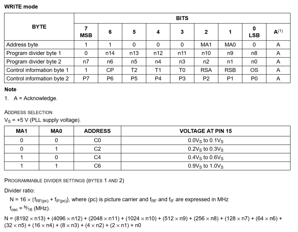 |
||||
| Volhout Guru Joined: 05/03/2018 Location: NetherlandsPosts: 3555 |
If you are using the audio output(and not the video output), be aware the audio carrier is 5.5 MHz offset. Volhout PicomiteVGA PETSCII ROBOTS |
||||
| lew247 Guru Joined: 23/12/2015 Location: United KingdomPosts: 1676 |
No I've bypassed the audio output by using an AD8307 chip which takes it's input from the vision IF signal from the tuner Edited 2023-05-21 22:21 by lew247 |
||||
| Volhout Guru Joined: 05/03/2018 Location: NetherlandsPosts: 3555 |
Hi Lew, Remember you asked me before to propose tuner settings for a TV tuner for 383MHz. Try those settings. Philips tuners typically have the same I2C register map. If you want more detailed help, please provide schematics of the circuit, and a datasheet for the tuner. That would help. It is possible the AD8307 output is coupled back to the tuner AGC pin to extend the dynamic range of the circuit. Volhout P.S. if you need me to write the code for the full project, provide me with a tuner for loan. I can get access to a signal generator and make sure it will work. P.P.S. there is benefit in using the audio output. It has 200kHz bandwdth, versus 5-6MHz for the video output. That lowers the noise floor, thus the measurement range. P.P.P.S. the PLL's crystal is typically 4MHz, so the values n0...n13 are multiples of 4MHz/16 = 250kHz, which I find strange. But it could with n0..n13 (14 bits = 2^14 = 16000. This could tuner to 4GHz. That is why I expect the step frequency on the PLL is 1MHz/16 = 62.5kHz. That would tune to 1000MHz. Better for a analog TV tuner. So each step is 62.5kHz. With 383MHz tuner and 33.4MHz IF you need to tuner the PLL to 416.4MHz, that is a divider set up for 416.4/0.0625 = 6662 This is binary 1 1010 0000 0110. n0=0, n1=1, n2=1, n3=0, n4=0, n5=0, n6=0, n7=0, n8=0, n9=1, n10=0, n11=1, n12=1, n13=0 Edited 2023-05-22 00:07 by Volhout PicomiteVGA PETSCII ROBOTS |
||||
| lew247 Guru Joined: 23/12/2015 Location: United KingdomPosts: 1676 |
@Volhout I want the full 6Mhz bandwidth of the video output, it's to detect ANY signal in that range I think I have it understood now thanks for your help You add the IF frequency to the desired frequency and divide it by the step size to give you a decimal number? You then convert that to Binary and then you read the binary from RIGHT to LEFT or do you read it left to right wnen filling this out Program divider byte 1 n14=1 ,n13=0 ,n12=0 ,n11=0 ,n10=0 ,n9=0 ,n8=1 Program divider byte 2 n7=1 ,n6=1 ,n5=1 ,n4=1 ,n3=0 ,n2=1 ,n1=1 ,n0=0 The IF frequency is actually 38.9Mhz as I'm using the Vision IF FI1216MK2.PDF I did actually consider this as the tuner AGC pin isn't connected internally in the FI1216 Tuner. IF I was using the TDA9800T I removed I could connect pin 12 of this chip to the ADC pin with a jumper for for this application it isn't going to do anything. Out of curiousity is there an easy way to convery this back to the frequency? 0x34 ; Prescaler first byte 0x60 ; Prescaler second byte |
||||
| Volhout Guru Joined: 05/03/2018 Location: NetherlandsPosts: 3555 |
As I read the datasheet, n0 is the least significant bit, n13 the mist significant. If you want to use the full 6MHz bandwidth, then you should know that TV signals where AM modulated, single sideband. the lowest frequency is the video carrier (15.625kHz), and higher the color carrier (4.43MHz), then at 5MHz, the video band stops, and at 5.5MHz the sound carrier is. So the tuner has a IF that goes from (see datasheet) 38.9MHz down to 33.4MHz (38.9-33.4 = 5.5MHz = audio carrier). The centre of this IF band is 38.9 - 2.75 = 36.15MHz (2.75 = 5.5 / 2) In case 383MHz is your desired centre frequency, then you should tune the tuner to 383 + 36.15 = 419.15MHz. Now your tuner will cover the band from roughly 380 to 386 MHz. It will have a shallow slope at 380MHz, and a sharp slope at 386MHz. Volhout Edited 2023-05-22 05:39 by Volhout PicomiteVGA PETSCII ROBOTS |
||||
| lew247 Guru Joined: 23/12/2015 Location: United KingdomPosts: 1676 |
I don't need the Audio IF I'm not using audio at all Or tuning anything other than one fixed frequency I actually want the centre frequency to be 382.5Mhz So using your logic my N number for the tuner is 348.25Mhz*16 = 6148 Converted to Binary this is 1100000000100 How do I do this from that binary number? Program divider byte 1 n14= ,n13= ,n12= ,n11= ,n10= ,n9= ,n8= Program divider byte 2 n7= ,n6= ,n5= ,n4= ,n3= ,n2= ,n1= ,n0= is n0 the number on the left of the binary number or the right of the binary number? I bet nobody would believe I was a fully qualified tv and radio engineer years ago before I damaged my brain Edited 2023-05-22 06:09 by lew247 |
||||
| Volhout Guru Joined: 05/03/2018 Location: NetherlandsPosts: 3555 |
 382.5 + 36.15 = 418.15 MHz (you must add the frequencies, not subtracts. Binary numbers have MSB left, LSB right. n0 is the rightmost bit. Other registers: CP = 0 (your tuner is fexed, does not change channel T2=T1=0, T0 = 1 OS = 0 RSA = RSB = 1 (62.5kHz PLL) Use mid band: P4=1 P5=0 P6=0 P7=1 P3=P2=P1=P0=0 Volhout PicomiteVGA PETSCII ROBOTS |
||||
| lew247 Guru Joined: 23/12/2015 Location: United KingdomPosts: 1676 |
Does this look correct (I know 6148 is the wrong number but this is just an examplse so I can try and understand) 6148 Converted to Binary this is 01100000000100 How do I do this from that binary number? Program divider byte 1 n14=0 ,n13=0 ,n12=1 ,n11=1 ,n10=0 ,n9=0 ,n8=0 Program divider byte 2 n7=0 ,n6=0 ,n5=0 ,n4=0 ,n3=0 ,n2=1 ,n1=0 ,n0=0 Or is it Program divider byte 1 n14=0 ,n13=0 ,n12=0 ,n11=0 ,n10=0 ,n9=0 ,n8=0 Program divider byte 2 n7=0 ,n6=0 ,n5=0 ,n4=0 ,n3=0 ,n2=1 ,n1=1 ,n0=0 Edited 2023-05-22 19:13 by lew247 |
||||
| phil99 Guru Joined: 11/02/2018 Location: AustraliaPosts: 1793 |
Perhaps this is a place to start. > dim integer n(15) Read n(0) to n(7) for the first byte and n(8) to n(15) for the second.> for y=0 to 15:n(y)=6148>>y And 1:? n(y);:next 0 0 1 0 0 0 0 0 0 0 0 1 1 0 0 0 > Reverse the order if necessary. Edited 2023-05-22 23:02 by phil99 |
||||
| lew247 Guru Joined: 23/12/2015 Location: United KingdomPosts: 1676 |
I do kinda get that and I got it all along What I DONT get is do you read the binary number from the LEFT or the RIGHT n0 is first digit on the LEFT, or first digit on the RIGHT? |
||||
| phil99 Guru Joined: 11/02/2018 Location: AustraliaPosts: 1793 |
Looking at your extract from the data sheet I don't think you need the individual bits. Just cut the divider number into 2 bytes. First byte = 6148>>8 Second byte = 6148 And 255 I think that will have the bits in the right order. > ? bin$(6148>>8,8) 00011000 > ? bin$(6148 And 255,8) 00000100 > Edited 2023-05-22 23:26 by phil99 |
||||
