Notice. New forum software under development. It's going to miss a few functions and look a bit ugly for a while, but I'm working on it full time now as the old forum was too unstable. Couple days, all good. If you notice any issues, please contact me.
mab1 Senior Member Joined: 10/02/2015 Location: United KingdomPosts: 239
Posted: 08:37am 28 Jul 2023
Copy link to clipboard
Print this post
Thanks Wiseguy and Solar mike.
I don't know much about these cores - evidently, but I think Poidas code does support 40kHz from memory, but will have to look into how i change that.
I did have a thought of getting this inductor and one made from a smaller aerosharp choke cobbled together, then see if i could compare them in use on the inverter - though i guess the aerosharp would prefer 20kHz.
I guess once I've determined how many turns i need I'll see if i have enough enamelled copper to of a reasonable size to make up a bundle - though i suspect I'd have to buy some. Although i seem to recall poida made use of 4mm solar wire? So maybe I'll try first with something similar and see if i get a reasonable efficiency - it's just using N in hand with smaller plastic insulated cable fills the space with plastic instead of copper - but perhaps that's a non-issue if the core prefers 40kHz.
poida Guru Joined: 02/02/2017 Location: AustraliaPosts: 1432
Posted: 06:45am 29 Jul 2023
Copy link to clipboard
Print this post
Most of the recent mppt code versions have the option to choose either 20kHz PWM (atcually 19200Hz) or 2x this, approx 40kHz Default is the "20kHz"
Switching losses are quite small, compared with the other losses so give it go at 40kHz The nice thing with going to 40Khz is you need only 1/2 the inductor energy storage so we can use 1/2 inductance for the same results as at 20kHz Since you seem a bit pressed for inductor design, this might get you over the line.wronger than a phone book full of wrong phone numbers
mab1 Senior Member Joined: 10/02/2015 Location: United KingdomPosts: 239
Posted: 08:41pm 30 Jul 2023
Copy link to clipboard
Print this post
Ok, thanks. Is the 20 / 40 kHz option selected from the calibration menu? Well i guess I'll connect it to the computer and find out.
I still might try and see how big a gap i can get the ferrites to work with, to get max Henrys whilst maintaining 50 - 60A saturation.
Trouble is work keeps getting in the way of experimenting
I couldn't get a working code working with 12C module. Please could you share that to me?how times flies
mab1 Senior Member Joined: 10/02/2015 Location: United KingdomPosts: 239
Posted: 04:30pm 21 Aug 2023
Copy link to clipboard
Print this post
I used the regular rs232 based serial interface (not i2c).
Here's a link to the page of Poidas 150A roll your own mppt thread - page37: if you scroll down a bit he posts a version of the code (.ino) written for 1c2, but i don't know anything else about it.
It may be worth reading through the whole thread as it explains why Poida went with rs232 serial rather than i2c.
On the subject of my own build (in case anyone's curious):
I've mostly finished construction of the mppt, wound my inductor with lots in hand of 0.71mm enamelled wire, but can't find any matches in the house - and the backup gas hob's igniter has gone belly up, so until i remember to buy some matches or something, i don't have a means of removing the enamel from the ends of my inductors wires. Edited 2023-08-22 02:31 by mab1
mab1 Senior Member Joined: 10/02/2015 Location: United KingdomPosts: 239
Posted: 09:18pm 28 Aug 2023
Copy link to clipboard
Print this post
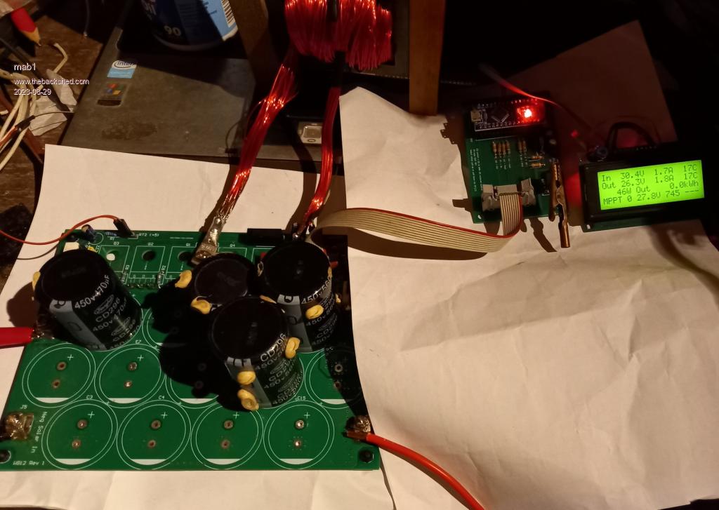
1st benchtop run of the whole mppt(except for the 12v supply/regulator - as the input voltage is planned as about 129V, i thought I'd use a small mains type).
The inductor's wound with about 20 in hand of .71mm dia wire (i found a 5000g roll in the accumulated junk pile). Not sure now how many turns - i was aiming for 24, and a gap of 5.6mm. saturation just above 59A, calculated 88uH.
Connected to the 24v battery, and one 30v 2A bench supply on the input.
It's ALIVE!!
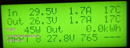
Two 30v supplies:
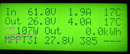
And (oo-err!) Four 30v supplies:
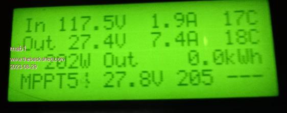
Not bad - running without a heatsink and nothing's getting warm . I think one of the bench supplies responds slowly on overcurrent which confuses the mppt into running at a slightly lower voltage (mppt should be with all of them maxxed out:129V ish).
And back down again.
I think there's a cal error on Vout - should be 26.2v, and i seem to be getting 1W in night mode. But i need to go back into cal anyway as I'm still running 20kHz and want to follow recommendations and run it at 40kHz.
Brilliant piece of kit Poida! thanks. I just need to get it finished. Edited 2023-08-29 07:24 by mab1
poida Guru Joined: 02/02/2017 Location: AustraliaPosts: 1432
Posted: 05:06am 29 Aug 2023
Copy link to clipboard
Print this post
don't worry about the 1W during NITE mode. I do all calculations in floating point so small offsets from the current sensors will give us not-quite-zero results when we expect zero. I "could" work a bit of code in there to show zero when we expect zero but it's better to have correct values, not nice values.wronger than a phone book full of wrong phone numbers
i am still searching Poidas instructions on calibration. plz helphow times flies
Murphy's friend Guru Joined: 04/10/2019 Location: AustraliaPosts: 671
Posted: 08:19am 02 Sep 2023
Copy link to clipboard
Print this post
It appears this project is more complex than you thought when you started it.
I suggest you read the *entire* post (many many pages) that poida wrote on this subject. You will find what you are searching for and learn a lot more in the process.
Asking for somebody to hold your hand searching posts while you are not bothering to check yourself is a big ask.
And please do not re quote entire posts just to add a one line question, do use the 'delete' key to strip pictures from your reply.
InPhase Senior Member Joined: 15/12/2020 Location: United StatesPosts: 178
Posted: 02:22pm 03 Sep 2023
Copy link to clipboard
Print this post
You should go take a nap and see if you feel better.
Have you used the search function on this forum? It sucks.
mab1 Senior Member Joined: 10/02/2015 Location: United KingdomPosts: 239
Posted: 09:23pm 03 Sep 2023
Copy link to clipboard
Print this post
SD: For info on how to access cal menu: IIRC, Bryans MPPT build has the instructions, and is only about4 pages - easier to look through. As to what defaults to keep? I set volts in/out zero amps and amps in/out, then i just looked down the list and changed anything that differed from what i wanted (i'm running a 24v system).
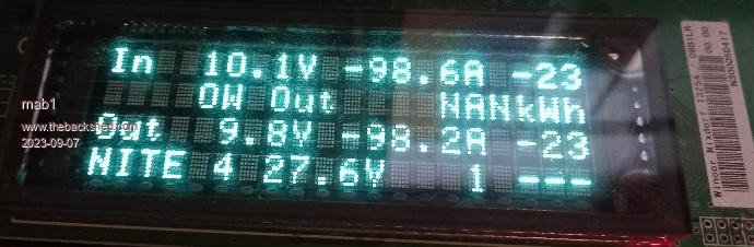
Connected up to the 'east' array this afternoon : first thing was that the display went blank as soon as it started working - could only get it to keep working if i dangle it outside the box at the mo' so need to add noise suppression. Also noticed the radio reception was affected - i guess common mode suppression on the pv wires needed.
Once i could read the display:
as the sun was headed west, i didn't get past 12A out, and was mostly <10A, but did notice the mppt seemed to be erring on the too-low voltage side c.f. what i would see from the gridtie inverter, sometimes way too low(Voc 154v, expected Vmp ~120 - 130, maybe 115 as light fades. Actually getting 109V at 10A out, dropping to 88v, but the odd 50v!).
The Iin zero had drifted to -0.2A so I'm wondering if that could throw off the MPP calculation at low power levels? Or could it be that i'm running higher voltage that the code was originally designed for? and i need to tweak something? Any ideas?
Edited to add:
I've tried a recal of amps, zeros and input volts (i was getting >100% efficiency to something was calibrated wrong ) and see what it does tomorrow morning with full sun. Edited 2023-09-04 10:46 by mab1
wiseguy Guru Joined: 21/06/2018 Location: AustraliaPosts: 1206
Posted: 01:47am 04 Sep 2023
Copy link to clipboard
Print this post
As an observation here, I actually concur with Murphy, I have had many naps in between trying to help SD and found the experience overall most frustrating. The not quoting multiple pictures and unneeded text is also great advice as it reduces clogging of a post (usually someone elses). I actually like to be accommodating and helpful but I expect useful feedback and at least for answers to be provided to questions that have been asked. for instance:
When time is taken by forum members to analyse, provide information and ask sensible questions but the time taken for a 1 word (useless) reply is essentially zero, you start to ask yourself, why am I trying to help someone who cant seem to be bothered to put in some basic effort themselves? Even given language barrriers, Google translate can't be blamed for these issues, others use it with quite reasonable success.
With regard to the search function that "sucks" have you informed the administrator on what does not work well and how it might be improved from a users perspective ? Constructive feedback is more likely to yield better results than just blunt criticism. Edited 2023-09-04 13:29 by wiseguyIf at first you dont succeed, I suggest you avoid sky diving.... Cheers Mike
mab1 Senior Member Joined: 10/02/2015 Location: United KingdomPosts: 239
Posted: 11:13am 04 Sep 2023
Copy link to clipboard
Print this post
Ok, I've been reading through mppt_scan part of the code: it appears to use iout and vout to calc power.
I know you ( Poida) said don't worry about small offsets (1W anyway ) but i seem to be having a small issue with zero offset on the output current sensor: i noticed when i recalibrated last night that the output zero had shifted to 0.4A, so i re- zeroed, but then when i connected to the battery again using a 10ohm precharge resistor, that shifted the zero -ve. And looking at it now after a morning of 30-35amps, (battery now at float and essentially zero amps) it's reading 0.4A again 11W.
Maybe this is upsetting the mppt algorithm?
Alternatively, I notice in the code there's a di variable with the remark "step size, i need to change this when ouput power increases too fast, when a battery is used for input".
I had the thought that at 150v the input caps hold a lot of energy - that maybe i need to slow the mppt scan slightly?
InPhase Senior Member Joined: 15/12/2020 Location: United StatesPosts: 178
Posted: 11:48am 04 Sep 2023
Copy link to clipboard
Print this post
He ain't wrong and neither are you. But he's overly bitchy sometimes, to the point of being degrading, like an old man on his porch yelling at squirrels. Edited 2023-09-04 21:49 by InPhase
mab1 Senior Member Joined: 10/02/2015 Location: United KingdomPosts: 239
Posted: 07:57pm 04 Sep 2023
Copy link to clipboard
Print this post
Not sure if the amps zero is a red herring or not (doesn't seem too bad now), so I've set it back to 20kHz just to see if that makes a difference tomorrow.
poida Guru Joined: 02/02/2017 Location: AustraliaPosts: 1432
Posted: 02:31am 05 Sep 2023
Copy link to clipboard
Print this post
wronger than a phone book full of wrong phone numbers
mab1 Senior Member Joined: 10/02/2015 Location: United KingdomPosts: 239
Posted: 08:20am 05 Sep 2023
Copy link to clipboard
Print this post
Thanks Poida!
This mornings experiment at 20kHz instead of 40 shows it finding the expected MPP just fine:
Although my inductor is heating up (top temp), i think that's resistive rather than frequency.
I was contemplating halving di to compensate for 416 steps vs 833 at 20kHz, but if changing dlay is better I'll try that 1st, but don't want to change too much at once as it just confuses things.
poida Guru Joined: 02/02/2017 Location: AustraliaPosts: 1432
Posted: 05:02am 06 Sep 2023
Copy link to clipboard
Print this post
let's look at power IN and power OUT, both should be the same with power out a bit less.
Pin = 122.7 * 8.0 = 982 W Pout = 26.5 x 36.1 = 957 W the power loss from voltage conversion is 982 - 957 = 25W conversion efficiency is the ratio and is 0.97 This is a good result. 25W loss when converting 1kW Maybe most of the 25W is consumed within the choke?
It's always worth the time to check Vin, Vout, Iin and Iout when it's running at this power level. This gives you a lot of confidence in the displayed results.wronger than a phone book full of wrong phone numbers
mab1 Senior Member Joined: 10/02/2015 Location: United KingdomPosts: 239
Posted: 03:01pm 06 Sep 2023
Copy link to clipboard
Print this post
Yes I'm quite impressed with the efficiency - particularly as I'm running 5:1 in:out ratio, so the schottkys are conducting for a high proportion of the time.
The calibration is fairly close now: vout is right, vin is actually reading a tad high, so the 122v is nearer 120v, and the Izeros are set so they drop back to 0.0 after seeing +30 - 40a (i did see 40A today - just ).
I set the throttle back to a higher temp for the inductor: it got up to 67°C (throttle back at 75°c) at 40A; i might put a fan on it. The heatsink is huge 10" x 10" x 2.5" fins. That got to 35° but the ambient in the shed is 28°.
It seems fine at 20kHz: I'll try 40kHz tomorrow. but i did change the mppt settings slightly for both frequencies so i want to see how they compare from full sun (morning) to shadow (pm).
I do have a completely unrelated question:- when you send characters to the lcd, you wait until baudc > 50. Am i right in thinking that raising this number will slow the data rate to the lcd but have no effects on the mppt?
The reason i ask is that i scored a job lot of 2nd hand vfd displays (shop till /point of sale units), mostly big 20x2 and one 20x4. They take serial ttl, 9600 baud, inverted logic, but the position commands are different, and using two instances of software serial on a nano to transfer the data struggles to keep up with the data flow.
poida Guru Joined: 02/02/2017 Location: AustraliaPosts: 1432
Posted: 08:08am 08 Sep 2023
Copy link to clipboard
Print this post
VFD displays.. cool yes, increase baudc and that will slow down the rate at which a 8 bit character will be sent. baudc is a wait counter, in baudrate. so the 50 = 50 clocks of 9600 baud.
// send one char out pin A4. First, get a character and put it in "blcd" and init state machine. if (go_lcd == 0 && baudc > 50) // not send as soon as possible, let the LCD digest the data with a delay here { .. ..
baudc = 50 is equivalent to 5 millisecond wait between characters. baudc is an "int" so it's 16 bit signed integer and that means it can only go up to 32,767 before overflow.wronger than a phone book full of wrong phone numbers
Page 2 of 3
Print this page
The Back Shed's forum code is written, and hosted, in Australia.


 . I think one of the bench supplies responds slowly on overcurrent which confuses the mppt into running at a slightly lower voltage (mppt should be with all of them maxxed out:129V ish).
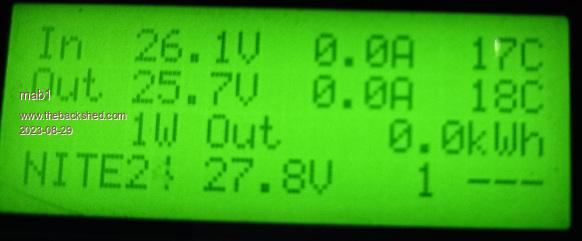
 SD: For info on how to access cal menu: IIRC, Bryans MPPT build has the instructions, and is only about4 pages - easier to look through. As to what defaults to keep? I set volts in/out zero amps and amps in/out, then i just looked down the list and changed anything that differed from what i wanted (i'm running a 24v system).
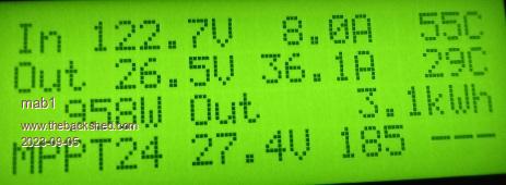
 ).
).