
|
|
Forum Index : Microcontroller and PC projects : PM audio LPF....wow....
| Author | Message | ||||
| stanleyella Guru Joined: 25/06/2022 Location: United KingdomPosts: 1643 |
a naked woman on a unicycle with a parrot? my Dutch is poor and the guy speaks too fast. Comments about Turkish people but words a comedian can say and it's funny? Edited 2023-06-02 02:05 by stanleyella |
||||
| stanleyella Guru Joined: 25/06/2022 Location: United KingdomPosts: 1643 |
The x-y idea didn't work because the signals need to be out of phase and no hantek controls sorted it.. pity.. but got a stable sine by using the normal trig, no jitter. you can see the spikes in the sine wave which I guess is noise, not all from picomite. ps The sound is great. brill! Fun! Edited 2023-06-02 04:00 by stanleyella |
||||
| ice2642 Regular Member Joined: 27/05/2023 Location: BrazilPosts: 81 |
Hello, I buyed a Silicon Chip Kit PicoMite VGA, this is coming I hope. This board as without sound, and I plan to build a little breakout board low pass filter using the scheme from manual. 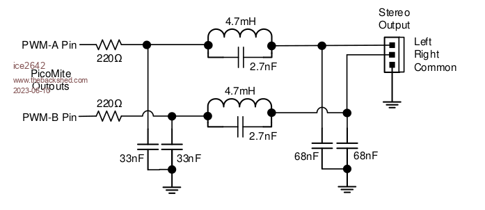 I am not very well knowledge in electronic, I know the basic of basic. Just to play with arduino and this things. May question is, is it the high type of inductor listed in the scheme? 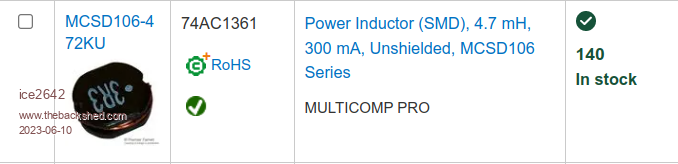 If yes, this is a good one or I can have best options? Second, the 33nf and 68nf in schema is it a capacitor? if yes, ceramic or what kind and with how much V? and about resistance, 220(the omega watch symbol) when buy is the label 220R? Sorry if my questions shows to be stupped. Thank you in advance, Best Regards, MMBasic 5.0707 on PicoMite VGA |
||||
| ice2642 Regular Member Joined: 27/05/2023 Location: BrazilPosts: 81 |
I found the MCP4822 maybe it will be best than a LPF. how is the best way to make a breakout board using this list plus the resistors to all work? 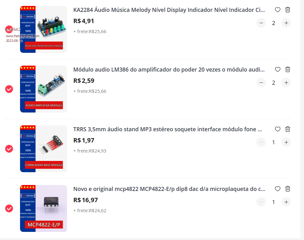 Thank you in advance. MMBasic 5.0707 on PicoMite VGA |
||||
| hitsware2 Guru Joined: 03/08/2019 Location: United StatesPosts: 705 |
https://www.amazon.com/Adafruit-Perma-Proto-Half-sized-Breadboard-PCB/dp/B00SK8QR8S/ref=sr_1_5?crid=1JY5MT75G3L0P&keywords=adafruit+proto+board&qid=1686339678&sprefix=adafruit+proto%2Caps%2C181&sr=8-5 my site |
||||
| Mixtel90 Guru Joined: 05/10/2019 Location: United KingdomPosts: 5726 |
For the actual I2C DAC all you need to mount is the chip, 2 resistors and 2 capacitors (although I'd recommend a resistor and capacitor to filter the supply as Peter did on the V1.1 board). That board will then pick up GND, 3V3, CS, MOSI and SCK from your Pico board. If you get a suitable connector you *might* be able to make it into a module that fits whatever GPIO connector is on your Pico board. It would then have GND, Left and Right running to your amplifier. It might be an idea to make this a 3.5mm jack but you don't have to. I can't really advise much else as it will depend on exactly what you are trying to do and what you already have available, as well as whatever constructional skills you have. Mick Zilog Inside! nascom.info for Nascom & Gemini Preliminary MMBasic docs & my PCB designs |
||||
| JohnS Guru Joined: 18/11/2011 Location: United KingdomPosts: 3659 |
Yes, capacitors. I guess any kind that's cheap (so will be ceramics I reckon) and it's low voltage so whatever you get will be fine I suspect. Yes. Don't know about the inductor, sorry. John |
||||
| ice2642 Regular Member Joined: 27/05/2023 Location: BrazilPosts: 81 |
Thank All you for answer. My idea with this PicoMite is build a little computer like TRS-80 color just for fun and remember gold days :) The sound I want use with tone, to make sounds for the programs that I made in the computer. Some games and this kind of code. I have some bread boards, A kit to make simple boards, speakers, some resistors, capacitors, etc... but if I needed I can buy some items since it not demand much investment. Best regards, Edited 2023-06-10 06:26 by ice2642 MMBasic 5.0707 on PicoMite VGA |
||||
| ice2642 Regular Member Joined: 27/05/2023 Location: BrazilPosts: 81 |
Hi friends, Just for testing while the components do not arrive, I assembled it with some components that I had here using approximation in the calculation fc=1/2pi r c and it suppressed the noise well. But it was popping in cycles of approximately 0.5s Knock Knock Knock.... Just for an intellectual exercise, what could be generating these pulses, I don't have an ocilloscope here to send more data about the wave. Pictures of the mess follow. 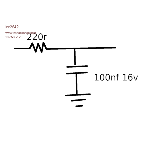 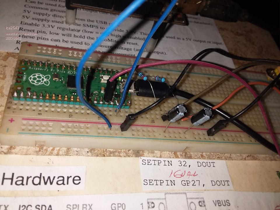 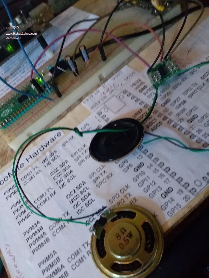 The litle code for making tones. 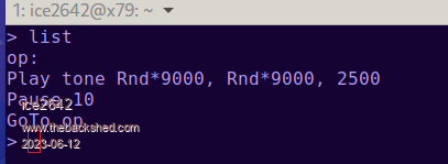 Thanks. Edited 2023-06-12 01:53 by ice2642 MMBasic 5.0707 on PicoMite VGA |
||||
| Mixtel90 Guru Joined: 05/10/2019 Location: United KingdomPosts: 5726 |
1) The capacitors that you've shown are electrolytic types - probably 100uF 16V. These are *far* too big in value, you want 100nF which are usually ceramic or polyester types. 2) Even with the correct values a single pole RC filter won't reduce the 44kHz carrier frequency by much because it's at such a high level when compared to the extracted audio signal. It's ok for quick experimenting on the bench, feeding something like a 35R headphone earpiece (but you'll need a series resistor of about 1K because it will be too loud). You could also use it with an amplified desktop speaker but you may need a volume control to prevent overload. Do not use it with a half decent amplifier and speakers that contain tweeters as something may get damaged. Mick Zilog Inside! nascom.info for Nascom & Gemini Preliminary MMBasic docs & my PCB designs |
||||
| ice2642 Regular Member Joined: 27/05/2023 Location: BrazilPosts: 81 |
Thank you. I need wait the correct capacitors arrive, here I just have this used. Best regards, edi I found some 103nf in an old power supply atx. 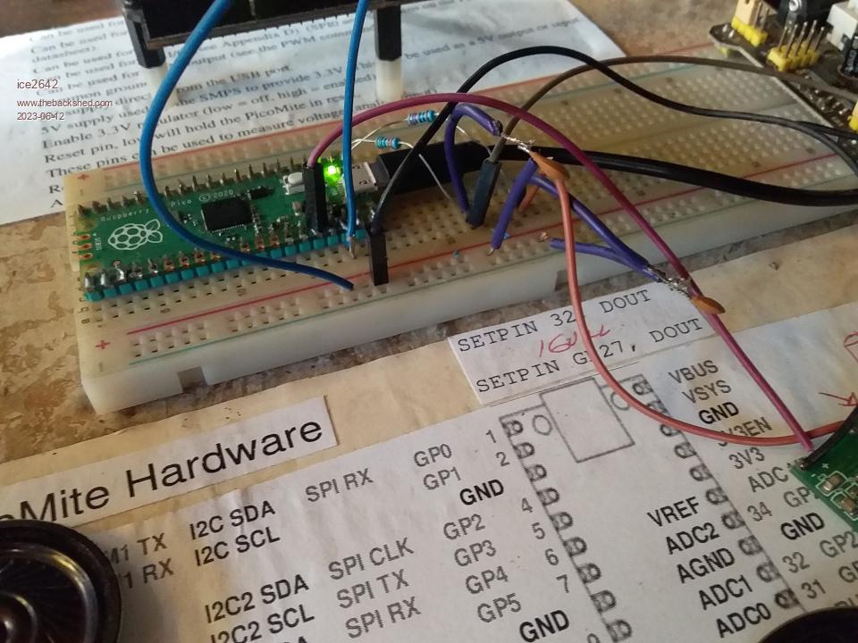 It wok, but now have a backgrownd sound when the tone is not running like a PX/radio interference. No more the tock tock pulse. Maybe in less than 50 years I have a HiFi sound :) Edited 2023-06-12 05:33 by ice2642 MMBasic 5.0707 on PicoMite VGA |
||||
| Turbo46 Guru Joined: 24/12/2017 Location: AustraliaPosts: 1593 |
@ice2642, If the presence of the 44kHz offends you then please use the filter that uses the inductor. It will remove most of it. Just remember that you cannot hear it, your speakers cannot reproduce it and your amplifier's frequency response will most likely begin to roll off after 20kHz or sooner. This forum is the only place I have seen where people have shown concerns about the carrier frequency. Unless you play vinyl records through an analogue amplifier, it is hard to think of any source of sound that does not come to you via some digital means or other, sometimes through several conversions. All require some form of carrier or modulation frequency. Even modern vinyl records are probably recorded and mixed by digital means. For me, the single stage RC filter as you have shown will do. I would use a higher value of resistor to reduce the load on the output pin and choose a capacitor to suit. Bill Keep safe. Live long and prosper. |
||||
| Mixtel90 Guru Joined: 05/10/2019 Location: United KingdomPosts: 5726 |
There are two major noise sources on the system. The first is the "computer hash". This is random square waves and pulses produced by the switching on the chip itself and radiated out via all connections to the chip. Some of the worst, on the supply lines, is reduced by the decoupling capacitors on the pcb. You can't do anything about this other than keep your leads as short as possible and route them directly out from the PicoMite pins, away from other signals as much as possible. The second noise source is the switching noise from the on-board 3V3 switching supply. This is *very* noisy and gets everywhere. The solution in this case is to disable the switcher by connecting 3V3EN to GND then powering the 3V3 pin from a linear voltage regulator. Usually a LDO type is used so that the input voltage can be 5V. I know you don't believe me, Bill. :) The LM4871 3W amplifier chip has a spec that ends at 20kHz because that's the accepted standard and its gain will be about 3dB-5dB down at that point. However the open loop gain is still less than 10dB down at 50kHz. That's not unusual for a modern chip amplifier. Now, you can't hear 44kHz, but you can amplify it. It's not a nice, kind sine wave either, it's a vicious 3V3 square wave with very fast edges when it hits the filter and it's a pig to get rid of. The audio after the filter is quite a bit less. So, you amplify the audio to get it to a usable level, but at the same time you are also amplifying any remaining carrier signal. You still can't hear that but it is still being fed to your speakers and, quite probably, has been returned to it's original square wave because the high level has overloaded the input stages of the amplifier. Tweeters are usually specified as something like 1.5kHz to 20kHz or sometimes 30kHz. However, these are usually -3dB points and there is still useful output above the max frequency. However, they can't reproduce 44kHz. But even if the diaphragm can't move fast enough the current in the coil heats it up. Tweeters usually run quite hot anyway and many use a ferrofluid to conduct heat away from the coil to the magnet assembly. This is because the tweeter windings have to be fine and lightweight so they are delicate. Slam them with a continuous high level distorted 44kHz square wave and they will not be happy bunnies. This is the theory. I'm not going to test it by sacrificing an amplifier and tweeter. I *do* know that rock band roadies often carry spare tweeters because the high level distortion effects put a heck of a stress on them and they are the first parts of a speaker cab to fail. And these are not delicate little domestic tweeters, these are big, meaty devices. Mick Zilog Inside! nascom.info for Nascom & Gemini Preliminary MMBasic docs & my PCB designs |
||||
| ice2642 Regular Member Joined: 27/05/2023 Location: BrazilPosts: 81 |
thank you Bill and Mick. Just to know if I get, Can I use a LM7805 for example, connected before the pin 40 or 38 (VBUS VSYS) for 5v power in, and the out of LM to the grownd (PIN28) for ex and the next pin to the sound board + ? I do not get yet the silicon chip board, I do not know how it power the pico. Best regards, MMBasic 5.0707 on PicoMite VGA |
||||
| Mixtel90 Guru Joined: 05/10/2019 Location: United KingdomPosts: 5726 |
VBUS is connected directly to the USB socket. If you are going to connect the USB then you must not power the PicoMite vua VBUS or you risk damaging whatever USB chip is powering the port. There is an on-board diode from VBUS to VSYS so you can feed 5V into VSYS without risking any damage. You can take a 5V supply from either VBUS or VSYS to power other 5V things. The LM7805 needs a minimum of 7V input. It's usable if you want to power a PicoMite from a 9V battery, for example. If you want a linear regulator for 3.3V then you need to find a LDO (low dropout voltage) type. These will work with 5V input to give 3V3 output. I would recommend not attempting to power the 3V3 line from a linear regulator while you are using a breadboard. That's because if the link between 3V3EN and GND is poor or drops out then the switcher will restart. I doubt if there will be a bang and magic smoke as the two 3V3 supplies try to battle it out, but I'd rather not take the risk personally. :) Alternatively, solder the link in on the PicoMite itself so there is no danger of it coming loose. Mick Zilog Inside! nascom.info for Nascom & Gemini Preliminary MMBasic docs & my PCB designs |
||||
| stanleyella Guru Joined: 25/06/2022 Location: United KingdomPosts: 1643 |
I use 5V & 3.3V linear reg boards and a dc supply. Your advice about 3.3V was alarming because I used them with bread board. 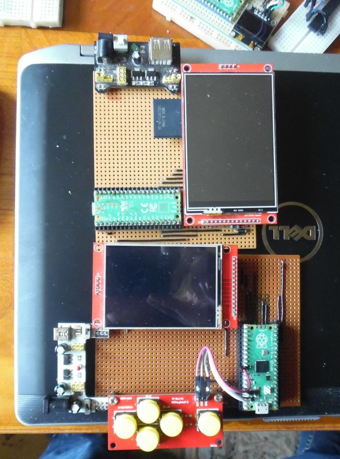 |
||||
| Mixtel90 Guru Joined: 05/10/2019 Location: United KingdomPosts: 5726 |
The reason I wouldn't expect a bang is because of the way the regulators work. Both are feedback devices so, if the output goes too high they reduce their output to try to correct it. One may get all the load on it because it has a marginally higher output than the other. Certainly you do want to shut down the switcher properly if you want lower noise though. Mick Zilog Inside! nascom.info for Nascom & Gemini Preliminary MMBasic docs & my PCB designs |
||||
| stanleyella Guru Joined: 25/06/2022 Location: United KingdomPosts: 1643 |
The 5v & 3.3V breadboard supplies has switches or links to change the voltage. It could be two 3.3V rails... I don't use the 5V rail. haven't checked the circuit board but a resistor in ground gives dual voltage? They ok and don't load the pico or usb port. oops I do use the 5V rail for the display but 3.3V to backlight... got to add 50R :( It will work on 3.3V if I short the ili 3.3V jumper but ok as is. As for audio noise or a-d noise is not a problem but never really was from running picomite from usb power from pc. The a-d keypad is ok but only tested from 3.3V lin reg. Don't want to start a new thread but how many people have problems with sound quality after the filter with the boost converter aka powering from usb? Edited 2023-06-13 08:59 by stanleyella |
||||
| stanleyella Guru Joined: 25/06/2022 Location: United KingdomPosts: 1643 |
I didn't realise the schottky diode in the external 5V supply was not built in :( |
||||
| Turbo46 Guru Joined: 24/12/2017 Location: AustraliaPosts: 1593 |
@ice2642, It seems that you have not read the Silicon Chip article but I suggest that you do. I think you can buy a PDF of the article or you can buy access to the online magazine issue. PM me if you want to  Maybe you should start a separate for your queries: @Mick, Comparing apples with oranges will not convince me I'm sorry. I know bands in general are brutal with their gear but comparing what they do with a few mV at 44kHz is quite a different kettle of fish. One of my amplifiers I built yonks ago was unstable and was oscillating, producing a rail to rail supersonic square wave. Both speakers survived. I stopped it eventually. A zobel network from memory. A test case of one proves nothing I know but... Volhout's filter design using the notch filter is clever and you would expect nothing less from him. I just happen to believe that it's not necessary. A storm in a teacup. Bill Keep safe. Live long and prosper. |
||||
