
|
|
Forum Index : Microcontroller and PC projects : ArmmiteF407 V5.07.02 betas - Library - No Battery and more.
| Author | Message | ||||
| matherp Guru Joined: 11/12/2012 Location: United KingdomPosts: 10195 |
The 5" SSD1963 is always a problem with power. The 4.3" is normally no issue and the 7" has a separate 5V supply for the backlight but the 5" needs external 3.3V in many circumstances |
||||
disco4now Guru Joined: 18/12/2014 Location: AustraliaPosts: 1000 |
Its definitely a power problem for me. I hacked the adaptor to allow selection of 3.3v from board or the separate 3.3v from via an AMS1117 from external 5V and with external power it works perfectly with 100% backlight. Switch it back and SDCard can't be accessed. As peter says its the 5" that has problems as its the biggest that does not have a separate 5V supply to the LCD Panel.  Latest F4 Latest H7 FotS |
||||
| ice2642 Regular Member Joined: 27/05/2023 Location: BrazilPosts: 82 |
Yes, the I2C will be slow compared to SPI for example, I think in the easy way to do and forget the speed. But if the esp32 work like one "custom chip", that the CPU just say what to do and the graphics chip work independent, maybe the velocity is ok. Like for example one commodore amiga working, the 68000 was very slow, but it just say to agnes* what to do, and in this way, it come fast. But what I am talking is just ideas and curiosity. Note: I do not remember if it is agnes, or other custom chip for ECS, sorry if it is other. Any way, thank you for answer :) MMBasic 5.0707 on PicoMite VGA |
||||
| TrevorH Senior Member Joined: 06/04/2018 Location: United KingdomPosts: 145 |
I have a result of sorts. With a separate 3.3v supply to feed the TFT, I still had the problem but I noticed if I disconnected the separate 3v3 the TFT was still lit but very dim. So the backlight was still drawing current from the armmite through the SSD1963 chip. To fix this I re-configured the TFT to "always on" for backlight and supplied the separate 3v3 to the LED-A pin. Now the TFT works fine with touch enabled. I still have one tiny problem, GUI calibrate shows on screen and T-IRQ drops when screen touched but the test doesn't progress (stays on first test point). Will check touch wiring next. Trevor |
||||
| disco4now Guru Joined: 18/12/2014 Location: AustraliaPosts: 1000 |
The Backlight control setting should always be 1963_PWM for the SSD1963. The Armmite will set the brightness via software commands. Page 89 on the manual has a picture. Latest F4 Latest H7 FotS |
||||
| TrevorH Senior Member Joined: 06/04/2018 Location: United KingdomPosts: 145 |
Fault on touch connections, I will try backtracking to SSD1963 PWM for backlight. 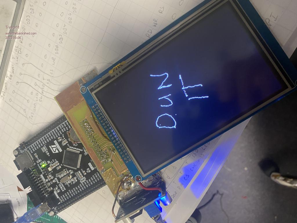 Sorry picture is upside down, I also swapped the linear Reg for a buck reg LM2596 which is much more stable than 7805. The 3v3 is from a ams1117 reg, 5v for 7" screens. Must do a new shield with new psu requirements. Trevor |
||||
| Mixtel90 Guru Joined: 05/10/2019 Location: United KingdomPosts: 7823 |
I've ordered some prototype PCBs to act as adapters for ArmMite F4 to SSD1963 5inch parallel displays. They should also be fine with other sizes but you may have to be creative with fixings. The main difference is that the Armmite F4 is a true piggy-back, all the IO pins face backwards, away from the display, for easy access. It will fit entirely behind a 4.3 inch display. The PCB includes a regulator for the backlight of the larger displays and a PS/2 keyboard socket. It also has a connector to take a ESP8266-01S or JDY-40, for which an adapter PCB is included. I also designed an adapter for the HC-12 but when I included it the board went above 100x100 and became too expensive! There is still space to fit the NRF24L01 as well if required. No gerbers yet. I want to test this before I release it. I may sell the three/four that I have no use for as mounting kits complete with the necessary screws and spacers, if anyone is interested. Cost will be pretty low, but postage may be an issue, particularly outside the UK. Normally I'd be happy to give them away, but I'm seriously short of hobby cash now! Mick Zilog Inside! nascom.info for Nascom & Gemini Preliminary MMBasic docs & my PCB designs |
||||
| TrevorH Senior Member Joined: 06/04/2018 Location: United KingdomPosts: 145 |
Hi Mick, I would certainly be interested in one, I have 5" and 7" displays to use. Trevor |
||||
| matherp Guru Joined: 11/12/2012 Location: United KingdomPosts: 10195 |
Mick Does the adapter support both motherboard variants? |
||||
| Mixtel90 Guru Joined: 05/10/2019 Location: United KingdomPosts: 7823 |
Yes. There are solder blob links for both, and also to reverse TX and RX for the comms modules should that be necessary. It shouldn,t, but I'm playing safe. :) Of course, that's providing that the only differences between the old and new TFT boards are the pins that we know about. Oh, and there's an option to power the F4 from incomimng 5V, the 3V3 regulator or neither (leaving it for the USB). 5V input pins are duplicated as a 2-pin polarized header and a 3.5mm barrel jack. Mick Zilog Inside! nascom.info for Nascom & Gemini Preliminary MMBasic docs & my PCB designs |
||||
| disco4now Guru Joined: 18/12/2014 Location: AustraliaPosts: 1000 |
There is a note in the manual to remove R25 (0 ohm resistor) if powering the board from an external 5V supply to stop it feeding back to the USB supplied 5V. There is no jumper to achieve this so removing R25 is how to achieve it. Latest F4 Latest H7 FotS |
||||
| Mixtel90 Guru Joined: 05/10/2019 Location: United KingdomPosts: 7823 |
That sounds like a good idea. I wonder about putting a schottky diode in instead, like the Pico? R25 is actually a 500mA fuse according to the schematic. Mick Zilog Inside! nascom.info for Nascom & Gemini Preliminary MMBasic docs & my PCB designs |
||||
| JohnS Guru Joined: 18/11/2011 Location: United KingdomPosts: 4033 |
It is (on the schematic), but on my V36 board it has just a 0 on it (which I guess a fuse wouldn't have). John Edited 2023-09-07 22:15 by JohnS |
||||
| disco4now Guru Joined: 18/12/2014 Location: AustraliaPosts: 1000 |
I think putting a schottky diode in instead was also a suggested solution way back. It should work, I tried but could not get one back in there, went for a blob of solder in the end. Latest F4 Latest H7 FotS |
||||
| Mixtel90 Guru Joined: 05/10/2019 Location: United KingdomPosts: 7823 |
Mine is a 0 link too. I don't seem to have any SMD diodes... I suppose the other way is to simply power the board from the external 3V3 regulator that's feeding the display's backlight. EDIT: I've ordered some diodes 'cos they were cheap. I think I can manage that size. :) Edited 2023-09-08 01:30 by Mixtel90 Mick Zilog Inside! nascom.info for Nascom & Gemini Preliminary MMBasic docs & my PCB designs |
||||
| pwillard Guru Joined: 07/06/2022 Location: United StatesPosts: 313 |
Adapter, since I ran into the *new TFT" issue as well.  UNTESTED |
||||
| okwatts Regular Member Joined: 27/09/2022 Location: CanadaPosts: 60 |
Looks useful, since I received a "New TFT" lcd panel but have an "Old TFT" development board. There will be an inevitable offset but given the situation where it is unpredictable which of each you might receive in an order I can live with that. |
||||
| Mixtel90 Guru Joined: 05/10/2019 Location: United KingdomPosts: 7823 |
I can now confirm that fitting a Schottky diode to the Armmite F407 instead of the 0R link (or 500mA fuse according to the circuit) works fine. I used a 1A 40V size SOD123 (1206), supposedly similar to a 1N5819. They were only about 2.40 UKP for 10 on ebay. I feel happier with the USB input protected. Mick Zilog Inside! nascom.info for Nascom & Gemini Preliminary MMBasic docs & my PCB designs |
||||
| barewires Newbie Joined: 13/04/2015 Location: United KingdomPosts: 32 |
On this page: https://www.thebackshed.com/forum/ViewTopic.php?TID=16169&P=5 The page navigation buttons are missing. |< < Page 5 of 5 |
||||
| disco4now Guru Joined: 18/12/2014 Location: AustraliaPosts: 1000 |
Scroll to the right, its there. The page is very wide so is off to the right of the screen. It happens when something very wide is added to a post. Edited 2023-09-14 20:21 by disco4now Latest F4 Latest H7 FotS |
||||
| The Back Shed's forum code is written, and hosted, in Australia. | © JAQ Software 2025 |
