
|
|
Forum Index : Microcontroller and PC projects : A SNES controller modification project
| Page 1 of 2 |
|||||
| Author | Message | ||||
| Mixtel90 Guru Joined: 05/10/2019 Location: United KingdomPosts: 5750 |
The cheap "SNES" controllers available from China aren't always what you expect inside. The cases seem to be reasonable, but the guts can actually be NES! Tom asked if it might be possible to convert them into "proper" SNES controllers by swapping the PCB. I couldn't resist a challenge like that, so here's a naked SNES controller in all its glory. 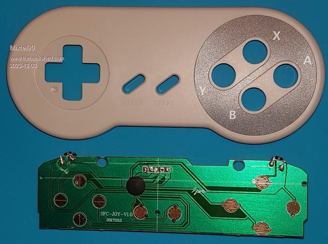 A bit of examination reveals that the left trigger button is in parallel with Y and the right trigger is in parallel with X. These pairs share a common from the chip, the other sides coming from A and B, with more chip connections. One side of all other buttons (including A and B) are grounded. Some sort of multiplexing seems to be going on. Connections from left to right are: VCC, GND, Latch, Clock, Data. In this case the wire colours are Red, Yellow, Green, Black, White respectively. The PCB is single-sided and just over 1mm thick. The trigger switches are standard 6mm tactile switches with the connections trimmed off one side. The remaining connections pass through holes in the PCB and are soldered. Mouldings in the case behind the switches prevent pressure damage. You may have noticed that I've scribed lines in the solder resist. I need reference points to get the hole positions right. I've spent quite some time on this today sorting the outline and some preliminary component positions out. Mick Zilog Inside! nascom.info for Nascom & Gemini Preliminary MMBasic docs & my PCB designs |
||||
| Mixtel90 Guru Joined: 05/10/2019 Location: United KingdomPosts: 5750 |
The case has plenty of mouldings in it to give support to the thin PCB under the action of high pressure fingers! There are no-go areas on both the bottom of the board, where you'd expect them, but also round every set of switch contacts. 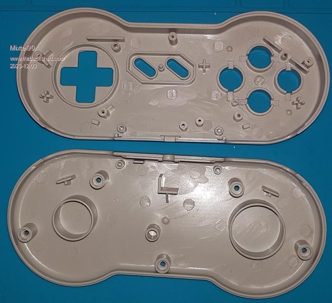 It looks like it might just be possible to do a through-hole design if components are mounted on the bottom side of the board. There is more height there (between the two big tubes in the bottom moulding). SMD on the other side might be more of a challenge. This is the basic PCB that we can work from: 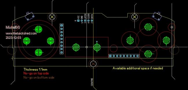 I've put the trigger switches on and tentative positions for two 8-way commoned resistor packs. I've done the drawing SL6 rather than CAD as that's where I'm going to need it and I can't directly convert between them. It's a pity because using CAD for this would have been easier. Edited 2023-12-03 19:33 by Mixtel90 Mick Zilog Inside! nascom.info for Nascom & Gemini Preliminary MMBasic docs & my PCB designs |
||||
| thwill Guru Joined: 16/09/2019 Location: United KingdomPosts: 3852 |
Thanks again for looking at this Mick. When I first saw this on my phone last night I was very confused, the photos in the first post looked like a controller with blue buttons and I definitely sent you one with multi-coloured buttons ... it took several minutes for my idiocy to pass  . .Best wishes, Tom Game*Mite, CMM2 Welcome Tape, Creaky old text adventures |
||||
| Mixtel90 Guru Joined: 05/10/2019 Location: United KingdomPosts: 5750 |
Ah, that's my new super el-cheapo silicon mat from AE. It makes a better photographic background than a cardboard box or a pile of bits of paper. :) Yep, the buttons (before they ended up back in the bag) are definitely coloured. Mick Zilog Inside! nascom.info for Nascom & Gemini Preliminary MMBasic docs & my PCB designs |
||||
vegipete Guru Joined: 29/01/2013 Location: CanadaPosts: 1084 |
I have one of these open on my desk and the internals are slightly different. The two large circles in the bottom shell are the same size (the smaller of your two, I think,) bosses are a bit different and the pcb (with white drop chip) is a simple rectangle, 109mm x 37mm. I'll post some photos later. Visit Vegipete's *Mite Library for cool programs. |
||||
| Mixtel90 Guru Joined: 05/10/2019 Location: United KingdomPosts: 5750 |
I can't see this being a generic board swap, unfortunately. as I suspect there are many variations in the mouldings. Especially in the positioning of fixing and switch pad locating holes. Mick Zilog Inside! nascom.info for Nascom & Gemini Preliminary MMBasic docs & my PCB designs |
||||
| stanleyella Guru Joined: 25/06/2022 Location: United KingdomPosts: 1652 |
off topic but cheap https://www.aliexpress.com/item/1005005242677970.html |
||||
| Mixtel90 Guru Joined: 05/10/2019 Location: United KingdomPosts: 5750 |
Cheap isn't as important as standard, I don't think. We need a controller that a) has a reasonable number of switches - probably 12 as an absolute minimum b) works at 3V3 reliably c) is easy to get d) is in, or can be in, a proper plastic case - not a 3D printed one e) is easy to interface f) is low cost TBH I think the genuine WII Classic is probably the closest I've seen to fulfilling these. The main problem is that the knock-off versions may not work at all. The price isn't incredibly cheap, but very few people will ever buy more than one so it's a bit of a moot point. It has the advantage that support for it is built into MMBasic on both the PicoMite and the CMM2. I managed to find some proper PCB sockets for these and I'm expecting delivery in the next day or two. Alternatively I like the idea of a DIIY controller that's easy to build. Something along the lines of the Game*Mite. That's what I'm experimenting with at the moment. I priced up the PCB and it works out at less than £2 each. There's no case though. =================================== Back on topic I have tentative designs for both through-hole and SMD now. I'm currently checking them before posting the results. :) It's been a bit of a struggle in both cases. Mick Zilog Inside! nascom.info for Nascom & Gemini Preliminary MMBasic docs & my PCB designs |
||||
| stanleyella Guru Joined: 25/06/2022 Location: United KingdomPosts: 1652 |
I ordered one as it got 10 buttons seems and is i2c, and so cheap. For personal use will be handy. |
||||
| Mixtel90 Guru Joined: 05/10/2019 Location: United KingdomPosts: 5750 |
I now have two different approaches to the problem. The copper side of the PCB has far less height available than the bottom, but is OK for SMD. Both sides have the problems of obstructions either abo or below the board - or both!. 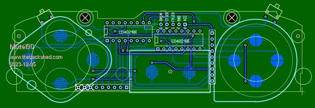 I don't mind this through-hole approach, but the space available for the resistor pack pins is tight. I've cheated on both versions. The official(?) circuit uses separate pullups for each of the four unused inputs. This is pointless for CMOS inputs so I've used a single resistor. The three unused ones can be simply ignored after cutting their pins off. This saves on length. Alternatively five single resistors could be commoned up. 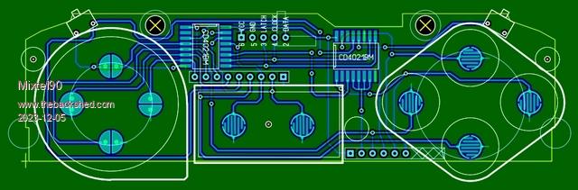 This is my preferred design, I think. I put the resistor packs on the bottom of the board again to avoid clashes with the flexible button pads. I think the SMD parts are also easier to get. Mick Zilog Inside! nascom.info for Nascom & Gemini Preliminary MMBasic docs & my PCB designs |
||||
| thwill Guru Joined: 16/09/2019 Location: United KingdomPosts: 3852 |
Hi Mick, Presumably the actual PCBs will not be rectangular, or are you planning on attacking them with a fret saw? As previously indicated I am happy to order/pay for PCB fabrication and components and send a share on to you. I was intending to wait until the New Year though, I should have guessed you would be done (twice) in the blink of an eye. Best wishes, Tom Game*Mite, CMM2 Welcome Tape, Creaky old text adventures |
||||
| Mixtel90 Guru Joined: 05/10/2019 Location: United KingdomPosts: 5750 |
I'd let JLCPCB cut the shape out. I don't think it will affect the price much as there are no internal cutouts. I'll do some gerbers and see how they are for price. As the 4021BM (SMD) chips are cheap I might get a price for boards with those ready mounted too. ----------- The bare board price for either option is £4.44 + postage + vat etc. for 5. That's cut to the silly shape. :) I couldn't find a way to get a price with the SMD chips mounted (I'm not using EasyEDA). No worries, this package size isn't terrible. . Edited 2023-12-05 03:00 by Mixtel90 Mick Zilog Inside! nascom.info for Nascom & Gemini Preliminary MMBasic docs & my PCB designs |
||||
| Mixtel90 Guru Joined: 05/10/2019 Location: United KingdomPosts: 5750 |
After reassembly I've just tested this particular Chinese controller on a PicoGAME V2. It is mapped as follows: red = bit 0 blue and right trigger = bit 0 rapid fire yellow = bit 1 green and left trigger = bit 1 rapid fire select = bit 2 start = bit 3 up = bit 4 down = bit 5 left = bit 6 right = bit 7 As you can see, despite it's appearance it is a NES controller. I gave it the full 16 clocks to make sure. . Edited 2023-12-06 02:46 by Mixtel90 Mick Zilog Inside! nascom.info for Nascom & Gemini Preliminary MMBasic docs & my PCB designs |
||||
| matherp Guru Joined: 11/12/2012 Location: United KingdomPosts: 8600 |
Mick If you are going to do this why not use a chip like the PCA9555PW. OK it won't be SNES compatible but will just need 2 wires and it's a single chip with built-in pullups, trivial to implement and up to 8 on the same i2c port!!! |
||||
| Mixtel90 Guru Joined: 05/10/2019 Location: United KingdomPosts: 5750 |
TBH that would be my preference. :) I'm only doing it this way because I was asked if I would. A I2C design would be easier to both build and interface. A little more fiddly if you want the I2C address changeable. My other little I2C controller, with a RP2040-Zero as the brain, can have its address changed and its pullups enabled/disabled just from the controller with no dip switches or anything. I could easily build other functionality in. Mick Zilog Inside! nascom.info for Nascom & Gemini Preliminary MMBasic docs & my PCB designs |
||||
| stanleyella Guru Joined: 25/06/2022 Location: United KingdomPosts: 1652 |
or any board with i2c like MCP23017, which I just figured for input an is cool as in it works. Used for out puts is fine. Standards are boring imho, standard input ok but how to achieve is user. I haven't soldered this yet but mcp23017 16 io pins. Could be any joy pad? 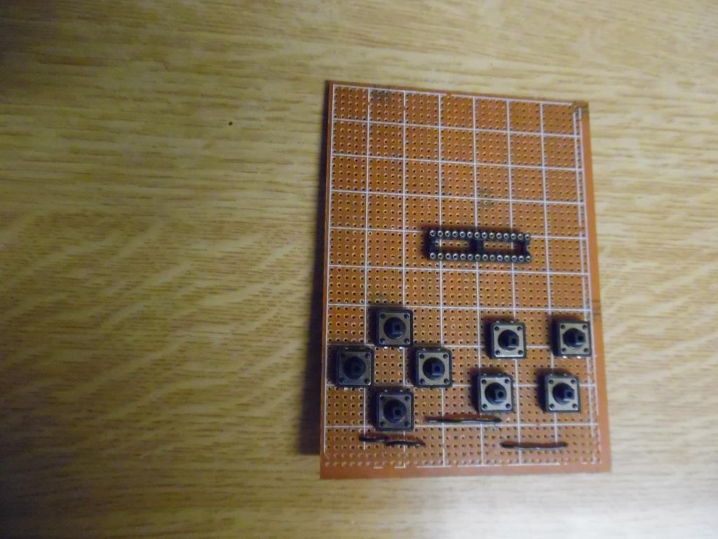 |
||||
| Mixtel90 Guru Joined: 05/10/2019 Location: United KingdomPosts: 5750 |
I think I can fit a RP2040-Zero into the SNES case. That would be interesting because I wouldn't need any pullup resistors or DIP switches to change the address etc. Mick Zilog Inside! nascom.info for Nascom & Gemini Preliminary MMBasic docs & my PCB designs |
||||
| Mixtel90 Guru Joined: 05/10/2019 Location: United KingdomPosts: 5750 |
I couldn't resist this. I2C version for I2C2 only because those are the pins that would be the wires available on the NES D9 plug. Embedded computing courtesy of a Waveshare RP2040-Zero. There is a WS2812B on the front controlled by GP10. This will normally be lit in one of the four button colours to indicate the I2C address. Hold down Select during power up and the LED lights up magenta. Press a colour button to select that channel. Hold down Start during power up and the LED lights white or green to indicate whether pullups are disabled or enabled. Press Select to cancel or Start to toggle. After any config it enters normal mode. It only returns two bytes: the first is all the bits on the direction d and colour buttons. The other has the two triggers, Start & Select. That's the general idea anyway. I couldn't use Reset rather than power up as Reset isn't out to a pin on the RP2040-Zero. 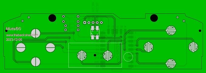 . Edited 2023-12-06 21:57 by Mixtel90 Mick Zilog Inside! nascom.info for Nascom & Gemini Preliminary MMBasic docs & my PCB designs |
||||
| Mixtel90 Guru Joined: 05/10/2019 Location: United KingdomPosts: 5750 |
This project is still continuing. :) I've ordered a pair of the very cheap SNES USB controllers from ebay. I want to see if the same PCB can be used with those. If it can I intend to provide the gerbers for the above through-hole version and the I2C version. I don't think many people will will want to solder the SMD one. I've added a switch to the I2C version to initialise the config system rather than using power-up. Just a tac switch that needs a pointy thing to operate it. I prefer that idea to having to run a config program as it means the controller can be used with any I2C host. Further plans are to allow re-mapping of everything. This would be very useful for those who are left-handed or who have disabilities. That would have to use a config program though, I think. I'm intending to simply remove the USB board and its cable and replace it with the new board and 1/2 of a 2m RJ14 4-core modem lead. That gives a flexible lead & a plug. The PicoGAME 4 will be able to accept two RJ14 sockets instead of the D9M as an option. These will be on the second I2C port (GP0 & GP1) so the WII controller will be able to be used at the same time! The RP2040-Zero is cheap on AE and the SNES controllers are cheap and the leads & connectors are cheap. I think this might be one of my more promising ideas. :) Mick Zilog Inside! nascom.info for Nascom & Gemini Preliminary MMBasic docs & my PCB designs |
||||
| thwill Guru Joined: 16/09/2019 Location: United KingdomPosts: 3852 |
Hey Mick, Just a quick line to say I haven't lost interest, I'm just otherwise occupied ... though you are going off piste. if want to hit me up for some funds for PCB fabrication as promised then drop me an email. Best wishes, Tom Game*Mite, CMM2 Welcome Tape, Creaky old text adventures |
||||
| Page 1 of 2 |
|||||
