
|
|
Forum Index : Microcontroller and PC projects : Sweetie-Pi-coMite VGA. Sorry, couldn't resist!
| Author | Message | ||||
| Mixtel90 Guru Joined: 05/10/2019 Location: United KingdomPosts: 5768 |
Here we are folks, the construction pack. Note! This is still an untested board. Build at your own risk. :) There are a couple of changes to the previous design: > I've (hopefully) improved the WII connector. > The WII controller has moved from I2C2 to I2C so I2C2 is available on the expansion connector. > I2C has been brought out to a 2-pin header so that other devices can be added to System I2C. > Silkscreen added & changed. I've included gerbers for both individual boards and for a block of four that you will need to saw up yourself. If you are ordering from JLCPCB it will cost you the same for 5 individual ones or 5 blocks of four. If anyone wants to try it I'll post the gerbers for a block of four but separated by lines on the outline layer instead of silkscreen. You might be able to get them V grooved like that. Don't ask me how though. :) Sweetie Pi-coMite VGA const pk.zip Mick Zilog Inside! nascom.info for Nascom & Gemini Preliminary MMBasic docs & my PCB designs |
||||
| lizby Guru Joined: 17/05/2016 Location: United StatesPosts: 3027 |
Glutton for punishment, I ordered the 4x--20 PCBs (after cutting) for $4.24 (pending engineering review--specs said the board width was 100.01mm). Mighty narrow space between boards. I don't have my bandsaw where I am, so I'll have to order a 4" diamond blade for the mini-tablesaw and use the shopvac for dust collection. Thanks for doing this board. PicoMite, Armmite F4, SensorKits, MMBasic Hardware, Games, etc. on fruitoftheshed |
||||
| Mixtel90 Guru Joined: 05/10/2019 Location: United KingdomPosts: 5768 |
I noticed that size too. The single board is shown as 50x50 though, and I simply put them together so there should be no error! JLCPCB don't seem to bother about minor things like that, luckily. :) There is a 0.8MM gap (in theory) between the copper areas on each board. You can still encroach into the copper slightly (actually, a mm or two across the middle where the big connectors are). It's not much of a gap, but if the blade height is set right I get a very fine cut. Far closer than most workshop band saws. Thanks for being my guinea pig. :) Mick Zilog Inside! nascom.info for Nascom & Gemini Preliminary MMBasic docs & my PCB designs |
||||
| JanVolk Senior Member Joined: 28/01/2023 Location: NetherlandsPosts: 104 |
Mick Thanks for sharing the schematic and PCB design. I looked at the schedule and saw some interesting things. The expansion port H2 in the schematic does not match the PCB design compared to the printed PCB. The K4 SD CARD connector in the schematic is correct, but probably GP numbers were chosen incorrectly when I look at the data sheet of the RP2040? In theory it should be like this: OPTION SDCARD GP29,GP2,GP3,GP4 ' CS=GP29,SCK=GP2,MOSI=GP3,MISO=GP4. If this is correct (not yet tested), then the Gerber files may also be incorrect? I also have trouble with the SPI bus but I remember it as follows. Master(RP2040) side MOSI = TX(MO) and the Slave side = DI(SI) or MISO = RX(MI) and the Slave side = DO(SO). Jan |
||||
| Mixtel90 Guru Joined: 05/10/2019 Location: United KingdomPosts: 5768 |
We'll no doubt find any errors out eventually. :) I'll check things tomorrow. I'll be on my way out for the evening very shortly. Connections to the expansion port are what they are. Assume the board is correct as they would be far too difficult to change. :) Note that the SDcard can use *any* pins. They don't need to be a hardware SPI port as it's bitbanged by the firmware. You just specify the ones used in the SDCARD option. Mick Zilog Inside! nascom.info for Nascom & Gemini Preliminary MMBasic docs & my PCB designs |
||||
| JanVolk Senior Member Joined: 28/01/2023 Location: NetherlandsPosts: 104 |
Mick Thank you for the quick answer. Learned something again. Jan |
||||
| Mixtel90 Guru Joined: 05/10/2019 Location: United KingdomPosts: 5768 |
The expansion port error is/was on the circuit diagram. I'd drawn a RUN pin, which is impossible on the RP2040-Zero as it doesn't have one. :) It was a silly error caused by starting out with the PicoMite VGA Basic drawing. Just ignore it and it'll go away eventually... SDcard SPI confuses me at times too, but luckily getting it right in this case is dead easy by changing OPTION SDCARD. :) Edited 2024-01-26 08:55 by Mixtel90 Mick Zilog Inside! nascom.info for Nascom & Gemini Preliminary MMBasic docs & my PCB designs |
||||
| Volhout Guru Joined: 05/03/2018 Location: NetherlandsPosts: 3582 |
Hi Mick, I have written some code that decodes the nunchuck and classic controller(*). I will use this to implement in the flappy game, but you could use it to test your boards once they are build. My classi controller, the - and + keys are SELECT and START. 'detect WII I2C controller and read classic controller/nunchuck registers 'assumes OPTION SYSTEM I2C is set Option default integer Const WII=&h52 'I2C device address 'init Dim x(5) SetPin gp3,din 'check if connected If Pin(gp3)=0 Then Print "no WII device plugged in, exit":End 'yes, go on, find out whay we connected Print :Print "Wii device connected" init_no_enc read_id id=((x(2)*256+x(3))*256+x(4))*256+x(5) 'show device select case id case &hA4200000 Print "WII nunchuck plugged in":cont$="WN" case &hA4200101 PRINT "WII classic controller":cont$="WC" case else print "unknown device, ID = ";hex$(id):cont$="KB" end select if cont$="WN" then 'nunchuck Print "X-joy Y-joy X-acc Y-acc Z-acc But-C But-Z" 'main loop Do 'get data from controller read_val 'decode data xa=4*x(2) + ((x(5)And &b11000000)>>6) ya=4*x(3) + ((x(5)And &b00110000)>>4) za=4*x(4) + ((x(5)And &b00001100)>>2) c_but=(x(5)And &b00000010)>>1 z_but=(x(5)And &b00000001) Print x(0),x(1),xa,ya,za,c_but,z_but Pause 100 Loop while inkey$="" pause 1:end end if if cont$="WC" then 'WII classic controller Print " L-joy R-joy analog trig direct contr cluster trigger" Print " X Y X Y lTrig rTrig < > ^ V - H + X Y A B * * l r" 'main loop Do 'get data from controller read_val 'decode analog data lx=x(0) and 63 ly=x(1) and 63 rtx=(x(2)\128)+((x(0) and 192) + ((x(1) and 192)\4))\8 rty=x(2) and 31 ltu=((x(2) and 96)+((x(3) and 224)\8))\4 rtu=x(3) and 31 'decode buttons l=(x(5) and 2)\2 r=x(4)\128 u=x(5) and 1 d=(x(4) and 64)\64 mi=(x(4) and 16)\16 pl=(x(4) and 4)\4 xx=(x(5) and 8)\8 yy=(x(5) and 32)\32 aa=(x(5) and 16)\16 bb=(x(5) and 64)\64 ho=(x(4) and 8)\8 lt=(x(4) and 32)\32 '=binary representation of ltu rt=(x(4) and 2)\2 '=binary representation of rtu zl=x(5)\128 zr=(x(5) and 4)\4 Print lx,ly,rtx,rty,ltu,rtu, print l;r;u;d;mi;ho;pl;xx;yy;aa;bb;lt;rt;zl;zr Pause 100 Loop while inkey$="" pause 1:end end if Sub init_no_enc I2C write WII,0,2,&h40,&h00 Pause 10 I2C write WII,0,2,&hF0,&h55 I2C write WII,0,2,&hFB,&h00 End Sub Sub read_id I2C write WII,0,1,&hFA I2C read WII,0,6,x() End Sub Sub read_val I2C write WII,0,1,&h00 Pause 1 'needed for nunchuck response.... I2C read WII,0,6,x() End Sub I know Peter implemented the classic controller in firmware, but not the nunchuck, so I worked around the firmware. Volhout (*)This is tested on my cheap clone classic controller that uses data format #01. That gives 6 bit resolution on the left joystick, and 5 bit on the right joystick, and 1 bit (only values 31 and 0) at the analog triggers. Edited 2024-01-28 01:46 by Volhout PicomiteVGA PETSCII ROBOTS |
||||
| Mixtel90 Guru Joined: 05/10/2019 Location: United KingdomPosts: 5768 |
Thank you, I can see that being very useful. :) Mick Zilog Inside! nascom.info for Nascom & Gemini Preliminary MMBasic docs & my PCB designs |
||||
| okwatts Regular Member Joined: 27/09/2022 Location: CanadaPosts: 51 |
I just wanted to report that I built up one of these (thanks to Lizby for the board) and everything I've tried seems to work. I have not tried the WII controller yet as I have to read up and find a game to check out. Thanks to you both I now have more PicoMite's than I need(I've lost count) but have them in non-VGA, VGA, and VGAUSB - genuine Raspi Picos, matherp's VGA v1.0a, LandBoard PicoVGA, Weact clones, PicomiteBackpack, Raspi2040 Zero etc. Now I need to start a club and get others interested locally! I don't want to be accused of being a Pico hoarder! |
||||
| lizby Guru Joined: 17/05/2016 Location: United StatesPosts: 3027 |
Start that club! The Sweetie-pi at about 25 cents U.S. per PCB would be great for an introduction to soldering / MMBasic / VGA / i/o (limited). I cut the boards apart with a sabersaw with metal blade held upside down. It wasn't pretty, but it worked. But I still haven't soldered up a board--I'm currently too distracted working on 12V, 24V, and 48V solar + battery setups in my shed. LiFePO4 battery prices are down nearly 40% from 2 years ago. Unfortunately my solar panels are small, and I don't have any real loads for them. PicoMite, Armmite F4, SensorKits, MMBasic Hardware, Games, etc. on fruitoftheshed |
||||
| okwatts Regular Member Joined: 27/09/2022 Location: CanadaPosts: 51 |
Just to show that I actually did build one I include a photo (Poor using phone camera) showing my construction skills(or not) warts and all. I used the resistors I had to hand hence the 1/4 watt ones that were close but not exact to those specified. R1 (2R2 in theory) is just a wire link on the underside of the board. Use and abuse as you will. The board was cutout of a panel of 4 donated by lizby. 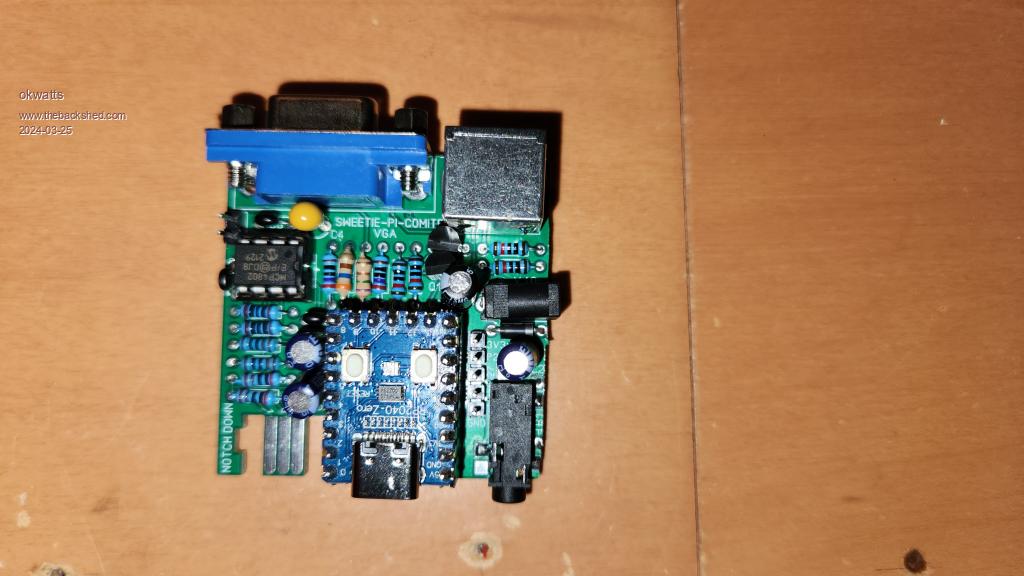 |
||||
| Mixtel90 Guru Joined: 05/10/2019 Location: United KingdomPosts: 5768 |
Many thanks. :) I've tweaked your pic a bit and added it to Peter's thread. I love seeing the results of people's builds of my boards. :) Sometimes we just use the components that are to hand. Nothing wrong in that. It's part of what engineering is about. Most micro SD cards wouldn't need R1 anyway. I put it in because it would be a pain to add it later if it was needed. Mick Zilog Inside! nascom.info for Nascom & Gemini Preliminary MMBasic docs & my PCB designs |
||||
