Notice. New forum software under development. It's going to miss a few functions and look a bit ugly for a while, but I'm working on it full time now as the old forum was too unstable. Couple days, all good. If you notice any issues, please contact me.
poida Guru Joined: 02/02/2017 Location: AustraliaPosts: 1392
Posted: 12:34pm 30 Jan 2024
Copy link to clipboard
Print this post
Two chokes. The above screens were from a 188uH choke, driven at 60V DC into a small toroid. This choke is a small Aerosharp fine Iron lamination with 22 turns. I also tried another choke, using the TDK E Core ferrite. 6 turns, and it is 65uH. So here are tests of both chokes.
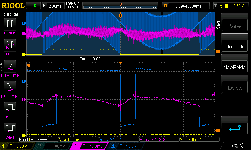
The following DSO captures have Yellow = 50 Hz square wave used for trigger Dark Blue = Voltage across the choke. 10V/div Purple is current through the choke. It's sensor is 0.0208V/Amps
First we see the 188uH choke
a idle and then with 200W resistive load.
I changed the current sense vertical attenuation when under load since it went off the screen.
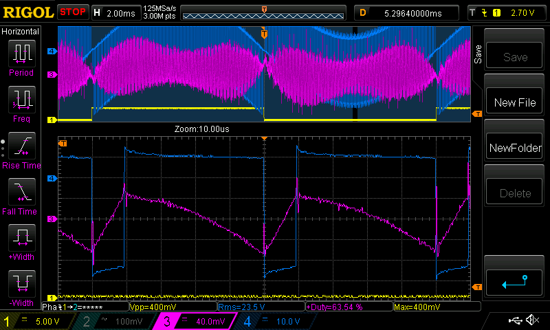
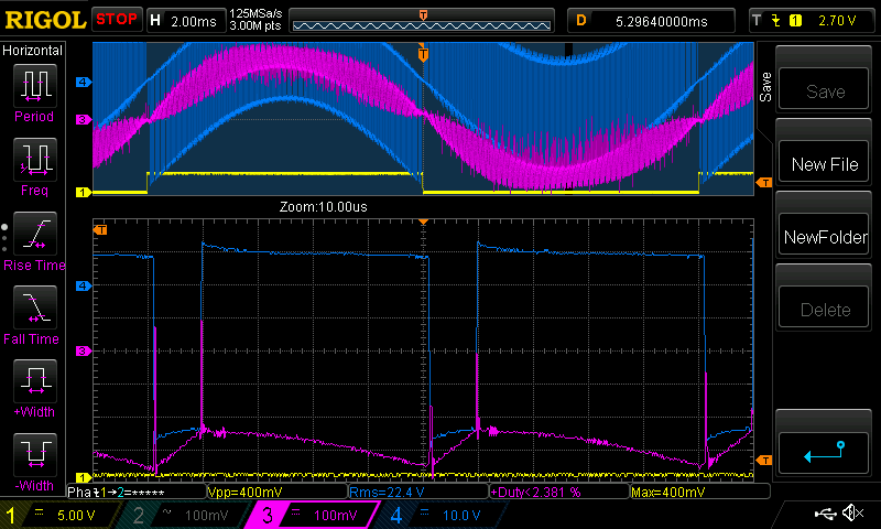
Next is the 65uH choke. Same test conditions.
what can we see from this? the voltage across the choke does not change when the AC load changes, in this case from zero load to 200W. We can see the higher current, and faster rising current trace from the smaller inductance of the 65uH choke. This is to be expected.
What I like to point out is the balance of Volts x time for both of the chokes. It must equal zero, or else it will rapidly approach saturation. (bang!) We can see it in all the 4 DSO captures. I will examine the first capture in this post. Looking at the Dark Blue zero position (it's DC coupled) we can see it goes -50 to -46V over 10 uS. Let's call it an average of -48V for 10 uS which is -480 V.uS This corresponds to the time the PWM is OFF When it's ON, it's on for 40 uS and it's voltage is about +12V on average for that time. this is 12V x 40uS = 480 V.uS It's the same as the first negative pulse. The running total of V.uS product is not increasing nor decreasing. This is good. I think this is really nice to observe.
But what is important to see is that the voltage across the choke does not change with AC load. It stays the same. The Volt.time product remains equal to zero too. The PWM width might change a small bit, due to the resistance of various parts of the system. This change is not important. This change of PWM due to AC load is minimised by the use of huge primary winding conductors, huge toroids, large FET banks etc. If some of us here did this test we probably would not see any change in PWM width due to the application of a 200W load. In the above captures you can just see it, an increase in PWM ON time of about 1uS with the 200W load.
I wonder if this might help us design the choke for our inverters. I hope so.wronger than a phone book full of wrong phone numbers
wiseguy Guru Joined: 21/06/2018 Location: AustraliaPosts: 1016
Posted: 12:54pm 30 Jan 2024
Copy link to clipboard
Print this post
Nice pics Poida - thank you. Any chance of an efficiency measurement for both chokes at 200W. My money is on the smaller 65uH choke as it seems to be doing more under load, storing and releasing energy, hope its not the 188uH one.
The purple spikes in my opinion may be related to excess dead time - dont get me wrong too much is boring and safe, too little though can get quite exciting.
The expanded part of the waveform appears to be very near the zero crossing point. If time permits could you please indulge me and also maybe look at the peak of the sine, And even at the 50% points it may be a little more revealing.
I would expect the textbook sawtooth you see in pic 3 upon more heavy loading should increase its p-p appearance, alas I am working for the next 2.5 days and will have no time to set up and see these answers. Edited 2024-01-31 08:11 by wiseguyIf at first you dont succeed, I suggest you avoid sky diving.... Cheers Mike
johansen Newbie Joined: 01/08/2014 Location: United StatesPosts: 2
Posted: 07:59am 31 Jan 2024
Copy link to clipboard
Print this post
so for what its worth folks.. it doesn't really matter if the choke saturates.
what matters is how much energy is lost when it does saturate. "swing chokes" where you have a tilted or stepped air gap in the core.. are still a thing and may be valid for the home brew sine wave inverter in which 90% of the time the load is minimal.
I was able to achieve a 10 watt no load idle current reduction from 23 watts to about 13 watts on a 1500 va sinewave APC ups, by adding a choke to the transformer. said transformer is used both for charging the battery and under load.
but the reason why probably wasn't because the ripple current was reduced. in fact it stayed the same. the apc ups sine wave ups has a variable pwm frequency and it dropped from on the order of 20khz to just 8 once i added the choke.
i found the best reduction was a 7 turn ferrite core of about 1" diameter core cross section with a small air gap. no doubt it would have saturated under load and increased losses but i wasn't able to measure that at the time.
i tried something like 7 turns of wire through several dozen mix 52 (the green blue iron powder cores) and the losses increased, not decreased, even though the inductance was similar.
Revlac Guru Joined: 31/12/2016 Location: AustraliaPosts: 964
Posted: 12:27am 03 Feb 2024
Copy link to clipboard
Print this post
That would have an E type transformer wouldn't it? I have a Belkin 1400VA but haven't checked, it was 24vCheers Aaron Off The Grid
Revlac Guru Joined: 31/12/2016 Location: AustraliaPosts: 964
Posted: 12:48am 03 Feb 2024
Copy link to clipboard
Print this post
A while back on one of my inverter builds I had wound a choke that appeared to work very well, nice sinewave as well, I say "appeared to work very well" so without knowing much its likely wrong, I don't have the test equipment others here have, so after some time I wound a few turns of small gauge wire around the choke core beside the large wire and connected the DSO to the ends if the small wire, the sinewave was there but a lot of sawtooth along it, perhaps this was a clue to the choke that wasn't up to the task?Cheers Aaron Off The Grid
wiseguy Guru Joined: 21/06/2018 Location: AustraliaPosts: 1016
Posted: 04:49am 03 Feb 2024
Copy link to clipboard
Print this post
Thank you for your post Johansen, but I feel I should make a few comments about your bold opening sentence, suggesting that saturation of the inductor "does not matter at all".
You do agree that an inductor actually does matter as far as reducing the idle power losses but that at higher power levels saturation is quite ok. I do applaud your experience and results with a specific computer type UPS but that should not be extended to be representative of all inverters.
If I don't reply to your post it might be construed that perhaps I concur with it or am in agreement with your experience. This post topic was essentially started as a discussion on how to calculate and design the best performing inductor for our typical high power inverters whilst avoiding saturation and consequential disasters.
I agree that a "swinging choke" is one answer, as they introduce a variable level of saturation depending on load. I hope we can find cost effective readily available off the shelf cores of new (or second hand) sendust types as solutions without any modification or too much compromise.If at first you dont succeed, I suggest you avoid sky diving.... Cheers Mike
wiseguy Guru Joined: 21/06/2018 Location: AustraliaPosts: 1016
Posted: 04:52am 03 Feb 2024
Copy link to clipboard
Print this post
Sounds more like it might have been a clue it was doing the exact task that was intended for it If at first you dont succeed, I suggest you avoid sky diving.... Cheers Mike
phil99 Guru Joined: 11/02/2018 Location: AustraliaPosts: 1813
Posted: 05:20am 03 Feb 2024
Copy link to clipboard
Print this post
That is a good way to read the AC component independent of the DC, especially if you know the turns ratio.
Yes, and for the ideal choke the 50Hz sinewave will be just a couple of volts at max. power and the HF sawtooth p-p will be a little less than the battery voltage, and decrease just a little from no load to almost full load. How much less than the battery voltage will depend on the transformer inductance, as some of the sawtooth voltage will be across that too. Edited 2024-02-03 15:27 by phil99
poida Guru Joined: 02/02/2017 Location: AustraliaPosts: 1392
Posted: 04:25am 04 Feb 2024
Copy link to clipboard
Print this post
finally got to do it.
188uH: idle or zero load: 60.0V DC & 0.150 Amps DC = 9.00 W ~200W load: 59.6V & 3.46 Amps = 206 W
65uH: idle: 60.1 V & 0.175 Amps = 10.5W ~200W load: 59.6 V & 3.47 Amps = 207 W
a note on measurements:
I used the Fluke 77 for DC volts measurements taken at the 30cm long 4 Gauge cable DC supply connections of the inverter. This negated any voltage drop due to long cables to the power supply. But more importantly, it is a DC measurement and there is some AC on this due to the DC bulk capacitor not being very big. It's only 10,000uF
The current measurement was done with the Fluke 87, again looking at DC amps.
The true values are probably different than those above BUT the error is likely to be the same for the two tests I did (idle and under load) so the results are comparable and I have confidence in the 3 significant figures.wronger than a phone book full of wrong phone numbers
KeepIS Guru Joined: 13/10/2014 Location: AustraliaPosts: 1399
Posted: 06:08am 04 Feb 2024
Copy link to clipboard
Print this post
That is similar to what I experienced, as expected the idle current went up more as I went down to around 40uH of total choke Inductance.
However, I was interested in surviving very, very high currents. I was aiming for 44uH but 40uH was as high as I could get with the high current windings needed and the size constraints of 12 large Toriod rings split over 2 chokes.
They take up some room.It's all too hard. Mike.
Godoh Guru Joined: 26/09/2020 Location: AustraliaPosts: 386
Posted: 02:32am 13 Feb 2024
Copy link to clipboard
Print this post
Can someone tell me what is the effect of the inductors saturating? I suspect that my 8010 aliexpress inverter is suffering from saturation. We have an electric car now, and the inverter will run the charger fine with an 8 amp output charging the car. If I try to draw 10 amps or more the inverter hums really loudly and goes out on overcurrent. The inductors that are in it are just a single torroid with a couple of turns on each that I took out of a dead 8kw Powerjack that was the source of the transfromer. I thought of the Powerjack as a 2.5 kw inverter at best, the 8kw on the cover was more likely the surge rating really. I am thinking of trying different inductors in the inverter to see if the loud hum disappears. Any input would be useful. I measured the current on my 3kw Latronics inverter when the charger was putting 11 amps into the car and the inverter was pulling about 108 amps from my 24 volt battery bank. Putting 8 amps into the car both inverters draw around 80amps. Pete
Godoh Guru Joined: 26/09/2020 Location: AustraliaPosts: 386
Posted: 04:32am 13 Feb 2024
Copy link to clipboard
Print this post
Just an update. I pulled the torroid inductors out of the inverter, and put in a 65mm E core inductor with 4 turns on it. It made no difference, although this time I watched the current when the charger was on. 85 amps when putting 8 amps into the car. Trying to put 11 amps in the current went up to 200 amps before the inverter shut down on overload. I am beginning the suspect my transformer. I used a powerjack transformer and only rewound the primary. It may have too many turns on the secondary. I think the original transformer worked out to have about 220 turns. The core is about 180mm od 90 id and 70 mm high. I have another core that I plan to rewind sometime, so I will wind that for 1 tesla and see how it goes. Pete
wiseguy Guru Joined: 21/06/2018 Location: AustraliaPosts: 1016
Posted: 05:35am 13 Feb 2024
Copy link to clipboard
Print this post
Did you use a gap in the 65mm Ecore ? With regard to the choke toroid/s was there anything written on the core/s?
The writing is usually on the outer side of the toroid cores. If it is a toroid/s from the common mode choke they are next to useless in this application.
If the E-core was not gapped it would likely have saturated early at the higher currents hence the 100A increasing to 200A, which is very scary - there was obviously 2kW trying to be turned into heat somewhere.
Personally I doubt that the transformer is actually faulty, but lets try to arrive at hopefully the right solution. It is my understanding and experience that transformers can work at much higher throughput than their continuous rating for short periods of time but heat will build up. Given the Ecore (Choke) gave such a bad result it does show that the choke is not optimised.If at first you dont succeed, I suggest you avoid sky diving.... Cheers Mike
Godoh Guru Joined: 26/09/2020 Location: AustraliaPosts: 386
Posted: 06:03am 13 Feb 2024
Copy link to clipboard
Print this post
Hi Mike the torroids were the original cores from the PowerJack inverter. They are small only about 70mm OD and 30mm high. I have a gap in the E Core inductor but maybe not big enough. Tomorrow I will try increasing the gap and see if that helps. The idle current with the E core inductor is only 0.5 amps, so only 12 watts which is great but the big current jump when trying to draw more than 2kw out of the inverter is pretty scary/ Jumping from 85 amps input to over 200amps for an increase in load from 2kw to 2.5 kw is fairly excessive. I will let you know how increasing the air gap on the inductor goes tomorrow. The power board on the inverter is supposedly a 5kw board. All I want is to be able to bump it up to 3500 watts if possible. Thanks for the help Pete
wiseguy Guru Joined: 21/06/2018 Location: AustraliaPosts: 1016
Posted: 06:52am 13 Feb 2024
Copy link to clipboard
Print this post
Ferrites have a very sharp knee of saturation. It would be better to stick with the iron-powder choke toroids for those power levels, do you have access to more of them? Try one less turn on the choke and see how it handles the 11A.
I think the E65 ferrites should be avoided unless you have 6 halves and can stack 3 of them together with a good air gap to try.
If not, condsider the iron core gapped choke, if that is what you can get your hands on more easily.
Then I would lean on renewable mark or noneya for further choke information on what they used.
I also wonder if the 2 - 2.5kW jump of around 10% is worth fighting for as it seems to work quite well at 2kW.
There is always 48V as a solution with a lot less input amps - lol. Edited 2024-02-13 16:54 by wiseguyIf at first you dont succeed, I suggest you avoid sky diving.... Cheers Mike
Murphy's friend Guru Joined: 04/10/2019 Location: AustraliaPosts: 600
Posted: 07:31am 13 Feb 2024
Copy link to clipboard
Print this post
Pete, now as the proud owner of an electric car why not take the plunge and build yourself a *real* inverter. That overrated Chinese stuff is just for keeping the headache pill makers in business.
Building an inverter from scratch is not rocket science, many posters here have done it. I had absolutely no idea how an inverter worked when I joined this forum. Now I have 6 home made inverters, 2 in use and the others for tinkering and improving. The latest version is very easy to build and packs a punch despite its small size (for my caravan).
A large portion of the parts I used came from scrapped inverters, so start collecting .
Godoh Guru Joined: 26/09/2020 Location: AustraliaPosts: 386
Posted: 08:24pm 13 Feb 2024
Copy link to clipboard
Print this post
Hi Mike , I understand that 48 volt would be better, but there are too many components to change. I would need to spend a lot of money on more batteries, new regulators,and new 48 to 12 volt converters. Just not on the table for me. I will have a look in the shed and see what other parts I have, for cores. I only have one 65mm E core. So will look into my torroid core collection.
Murphy's friend, I get the inverter build may be the way to go. Ideally I would like to build something that can easily manage 3600 watts continuous. I do have a transformer core that needs winding so that part is sorted. I have done the calcs for that core and all I need to buy is the magnet wire for the secondary windings and then spend some time winding it.
What sort of architecture would you suggest for the inverter. I have seen Warpverter builds here and I think the others are Madness designs. Warpverters sound very complicated but I have not read enough about them to get my head around them. Thanks for the input Pete
Revlac Guru Joined: 31/12/2016 Location: AustraliaPosts: 964
Posted: 09:44pm 13 Feb 2024
Copy link to clipboard
Print this post
Pete, Correct me if I'm wrong, isn't this inverter the same one that starts and runs the air compressor and many other loads quite well, never had issues running things? Just its playing up when trying to charge the car, makes me wounder what has changed.Cheers Aaron Off The Grid
Godoh Guru Joined: 26/09/2020 Location: AustraliaPosts: 386
Posted: 10:03pm 13 Feb 2024
Copy link to clipboard
Print this post
Hi Aaron, yes this inverter runs my air compressor, MIG welder, any power tools I have no problems. But trying to pull over 8 amps for the car charger totally overloads it. From what I understand the car charger just sends a square wave pulse to the car to tell it that there is power available, then connects the 230 volts AC to the cars onboard charger. I will have to have a better look, re what voltage the charger is pulling the inverter down to when it goes into overload. My 3kw Latronics inverter runs the car charger at 11 amps no problem, it doesn't go into overload at all. It is just running very close to its maximum load when doing so. I would prefer not to run the inverters so hard, so was looking to use the home made inverter instead. Supposedly it is a 5kw powerboard. So should handle it well. Off to town this morning, so will do some more tests later and get back.
What happens is the car charger ramps up the current, once it gets to full load of 11 amps the 8010 inverter growls and goes out on overload. I will get my oscilloscope out and see what it happening to the output waveform when that happens. Thanks Pete
wiseguy Guru Joined: 21/06/2018 Location: AustraliaPosts: 1016
Posted: 10:21pm 13 Feb 2024
Copy link to clipboard
Print this post
How many FETs are on the power board in total and what type are they ? If the answer is described in previous posts I haven't looked - often when I try it can take ages and still not find despite many trips down many rabbit boroughs. If at first you dont succeed, I suggest you avoid sky diving.... Cheers Mike


 I don't have the test equipment others here have, so after some time I wound a few turns of small gauge wire around the choke core beside the large wire and connected the DSO to the ends if the small wire, the sinewave was there but a lot of sawtooth along it, perhaps this was a clue to the choke that wasn't up to the task?