
|
|
Forum Index : Microcontroller and PC projects : Colour Maximite 1.5? or something
| Author | Message | ||||
| matherp Guru Joined: 11/12/2012 Location: United KingdomPosts: 8600 |
doesn't work because of the mounting holes |
||||
| Volhout Guru Joined: 05/03/2018 Location: NetherlandsPosts: 3565 |
Maybe it fits... You could put the audio connector in it's old place. Alternative: change the 40 pin connector to something like 30 pin. The audio, video pins you would not route to the 40pin header anyway (like the non-USB board version 1.7). 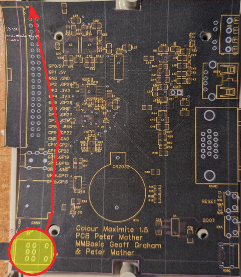 Edited 2024-03-08 05:01 by Volhout PicomiteVGA PETSCII ROBOTS |
||||
| matherp Guru Joined: 11/12/2012 Location: United KingdomPosts: 8600 |
This seems like a good compromise. They haven't got stock of the pot/switch (RK0971224Z0H) so it doesn't show it but it is widely available. Also the RTC is showing out-of-stock again - they had 3000+ last time I looked. 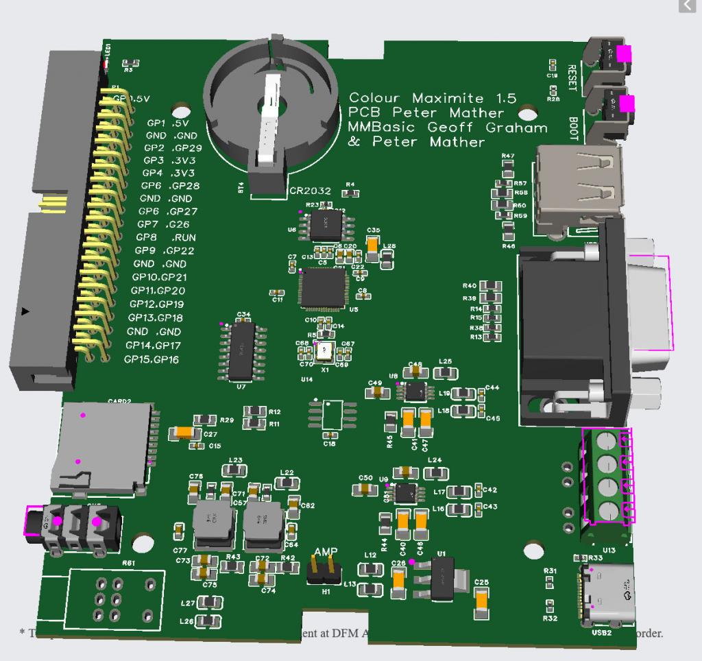 Edited 2024-03-08 05:29 by matherp |
||||
| Volhout Guru Joined: 05/03/2018 Location: NetherlandsPosts: 3565 |
Agree !! Volhout PicomiteVGA PETSCII ROBOTS |
||||
bigmik Guru Joined: 20/06/2011 Location: AustraliaPosts: 2870 |
Hi Peter, Volhout, I can't see what doesn't quite fit, it appears that all external parts fit quite well. If you want more space you could opt for a Vertical USB-A and fit the 3.5mm audio jack on the rear panel (maybe next to the speaker jacks) Regards, Mick. . Edited 2024-03-08 09:36 by bigmik Mick's uMite Stuff can be found >>> HERE (Kindly hosted by Dontronics) <<< |
||||
| Volhout Guru Joined: 05/03/2018 Location: NetherlandsPosts: 3565 |
Hi Peter, This is a personal preference. When possible, dual footprint the LED with the previous (expensive) part. The right angle SMT LED may be a nice solution for cost and automatic placement, but in a housing you may need a light-pipe embedded in the front panel to have an appealing ON LED. A simple 3mm LED that can be mounted in 2 through-hole pads is far simpler (it combines LED and light pipe in one construction). For BigMik it is more work, so he will like the SMT part. I myslef would remove it and place a 3mm LED. And soldering a 3mm LED to the SMT pads is basically destroying the board. Since you seem to have lots of board area next to the coin battery, maybe add a "ancient" LM7805, so you can power the board from 12V. That brings it in line with CMM1. My personal view: The BOOT switch was internal in the CMM1 and CMM2 (except your latest G2V2). Normal users would not use it that often (one per year ?) except the guys that test al the beta's. Similar the RESET switch (I did not even install it on my boards, I just re-power or CPU RESTART). But others may have a different vision on this. Volhout PicomiteVGA PETSCII ROBOTS |
||||
| matherp Guru Joined: 11/12/2012 Location: United KingdomPosts: 8600 |
LED holes - no issue If I move the boot button internally then I can perhaps shrink the board to 100x90mm which would save a few pennies |
||||
| Mixtel90 Guru Joined: 05/10/2019 Location: United KingdomPosts: 5751 |
If the boot button is through-hole you could mount it on the bottom of the board as an option and access it through a hole in the bottom of the case if needed. The PCB mounting pillars are high enough to allow this. I like to put a little hole in the middle of the pads just for marking the hole position in the case. I'm not a fan of the vertical USB-A sockets as there are both RH and LH versions available and some of the cheap vendors don't tell you which version they are selling (they may not know). Edited 2024-03-08 19:46 by Mixtel90 Mick Zilog Inside! nascom.info for Nascom & Gemini Preliminary MMBasic docs & my PCB designs |
||||
| lizby Guru Joined: 17/05/2016 Location: United StatesPosts: 3025 |
It might not be a problem since the number of people who would hand-solder this board is likely to be zero. PicoMite, Armmite F4, SensorKits, MMBasic Hardware, Games, etc. on fruitoftheshed |
||||
| Mixtel90 Guru Joined: 05/10/2019 Location: United KingdomPosts: 5751 |
Good point. :) Mick Zilog Inside! nascom.info for Nascom & Gemini Preliminary MMBasic docs & my PCB designs |
||||
| bigmik Guru Joined: 20/06/2011 Location: AustraliaPosts: 2870 |
Hi Volhoult, All, I am curious as to why you would think that? I personally would never use any LED designed to be seen externally that wasn’t a standard THP LED, even when I built CMM2’s I used 2 x 3mm LEDs for power and SD access instead of the specialised dual RED/GREEN device. I understand that Peter is trying, quite successfully, to get a PCB that is entirely made by JLC but I still wouldn’t use an SMD LED in place of a 10second soldering job for a standard THP 3mm (or 5mm). No criticism to either Volhoult or Peter here. Regards, Mick Mick's uMite Stuff can be found >>> HERE (Kindly hosted by Dontronics) <<< |
||||
| matherp Guru Joined: 11/12/2012 Location: United KingdomPosts: 8600 |
Here is the final routed version. I'll get a couple made and then release the gerbers and dxf for end-panels to fit the MULTICOMP MCRM2015S CASE CMM1.5.pdf 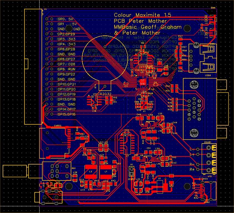 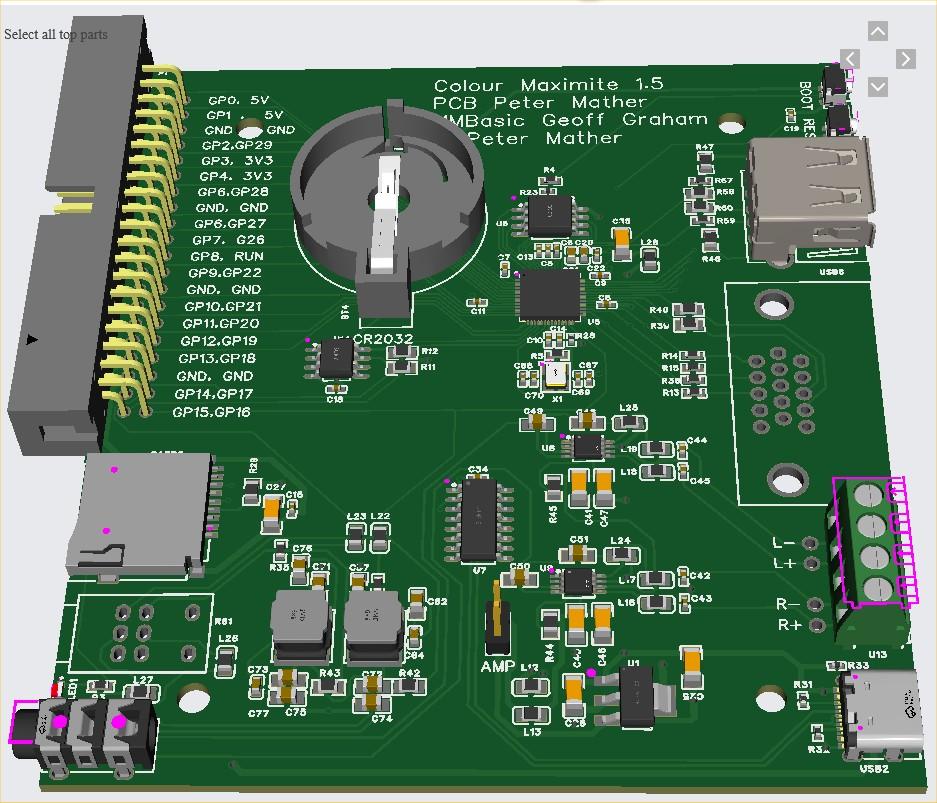 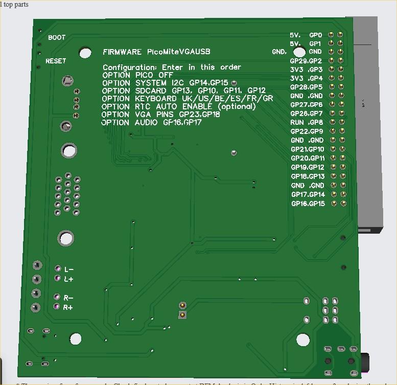 |
||||
| Amnesie Guru Joined: 30/06/2020 Location: GermanyPosts: 384 |
I really like how the PicoMite evolved and now even USB is possible. But there is one crucial thing why I don't like this design (but that's maybe just me!). What is the benefit of the whole Raspberry Pi Pico attempt? It is capable and dirt cheap, you can try things out and do stuff without beeing too careful. If something went wrong with the RP2040 Microcontroller on this board it will be a nightmare to change the IC. At least for a lot of people. In fact, this is the only reason I am still using my own iteration of the non-USB (VGA) version. I am well aware that Peter choose to put the microcontroller right on the PCB, since it frees up some PINS, which are not accessable on the original Rpi Pico board. My idea would be following: just designing a second PCB like the original RPi Pico board with those free PINs / which fits your design needs. This way EVERYONE can just replace the microcontroller board if something went wrong. Problem is, that this whole new design is not that cheap to replace like just the microcontroller board. This is the only thing I would do different. Just as an input  ... it is just an idea. I am not trying to suggest that Peter should re-design it, at least not for me, since I am doing my own PCB work. But maybe anyone thinks the same. Who knows :) ... it is just an idea. I am not trying to suggest that Peter should re-design it, at least not for me, since I am doing my own PCB work. But maybe anyone thinks the same. Who knows :)Greetings Daniel Edited 2024-03-14 04:41 by Amnesie |
||||
| Mixtel90 Guru Joined: 05/10/2019 Location: United KingdomPosts: 5751 |
Sometimes it's just fun to design things in a certain way. There doesn't have to be a reason. :) This board, as you say, allows the system to use more GPIO pins (all the pins, in fact) and all at once - unlike Pico clone boards which have their own limitations even if they have more GPIO pins. Having the board assembled by the PCB manufacturer allows the cost to be kept down at the expense of servicability. Yes, blowing up a GPIO pin means that you've lost it, but you can't have all of them available unless you build using the RP2040 without it being tied to someone else's idea of a module. You could design round the RP2040 Stamp from Pimorini if you wanted something with a user-replaceable RP2040, but the cost is pretty high. Mick Zilog Inside! nascom.info for Nascom & Gemini Preliminary MMBasic docs & my PCB designs |
||||
| matherp Guru Joined: 11/12/2012 Location: United KingdomPosts: 8600 |
Daniel The Pico is fine for a standard VGA build but less than ideal for the USB variant. A USB keyboard will always want a USB-A to plug into. yes, you can use an adapter onto the micro-usb but you will soon find that you start to get a poor connection or accidentally pull the micro-usb off the board. Then you need to supply power to the Pico VBUS pin and add a usb-uart. I think the all-in-one board is much better and the cost is less than £25 fully assembled including 16Mbytes flash, RTC, amp, headphone jack etc. The idea of this build is a self-contained boot-to-basic computer (CMM1.5). Power-on and it works. The board is designed to fit into a readily available, cheap case and can be ordered ready-to-run from JLC - no soldering required. Horses for courses  Edited 2024-03-14 07:19 by matherp |
||||
| JohnS Guru Joined: 18/11/2011 Location: United KingdomPosts: 3675 |
I can see merit in Daniel's idea - but it would be another board (well, mobo & CPU board pair), really. This one is what it says it is (and good value by the looks of it). John |
||||
| Volhout Guru Joined: 05/03/2018 Location: NetherlandsPosts: 3565 |
Cmm1 and Cmm2 are also chip soldered on board. PicomiteVGA PETSCII ROBOTS |
||||
| Mixtel90 Guru Joined: 05/10/2019 Location: United KingdomPosts: 5751 |
So is your monitor, blue-ray, power supply.... :) Mick Zilog Inside! nascom.info for Nascom & Gemini Preliminary MMBasic docs & my PCB designs |
||||
| phil99 Guru Joined: 11/02/2018 Location: AustraliaPosts: 1805 |
@Amnesie if you can make your own PCB use Peter's circuit with a "RP2040 16M Purple" module. It has the extra pins and 16Mb flash. Same size as a standard Pico but different pin layout. Less ⏚ pins to make room for the extra GPIO pins. A little cheaper too, eg. https://www.aliexpress.com/item/1005006290969946.html |
||||
| Mixtel90 Guru Joined: 05/10/2019 Location: United KingdomPosts: 5751 |
You have to be careful with the clones if you want to access the on-board USB. The Pico brings out D+ and D- to test points under the board. You can run these to your own USB socket. I don't know about the purple board, but the YD-RP2040 (the black board) doesn't make those connections available so you have to use a USB-C connection to your USB keyboard and/or hub. Such hubs are available, but they are harder to find than those with a USB-A plug. You also need to be able to make 5V available on that socket. Once again the YD-RP2040 doesn't work as VBUS isn't brought out to a pin. Edited 2024-03-14 08:21 by Mixtel90 Mick Zilog Inside! nascom.info for Nascom & Gemini Preliminary MMBasic docs & my PCB designs |
||||
