
|
|
Forum Index : Microcontroller and PC projects : GameBoy Emulator for PicoMiteVGA HW
| Page 1 of 3 |
|||||
| Author | Message | ||||
| javavi Guru Joined: 01/10/2023 Location: UkrainePosts: 565 |
Adapted the pico-gameboy firmware of the GameBoy emulator for the PicoMiteVGA board https://github.com/xrip/pico-gameboy 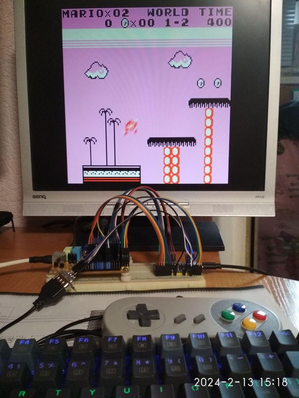 On the SD card, create a folder GB: in the root, put the ROM (*.gb *.gbc) files there. Controls: PS/2 Keyboard & NES Gamepad UP, DOWN, LEFT, RIGHT - Arrow keys A Button - Z key B Button - X key START - Enter key SELECT - Backspace key SELECT+START in game menu The NES gamepad is connected like the PicoGAME VGA board NES_GPIO_CLK= GP3 NES_GPIO_LAT= GP2 NES_GPIO_DATA= GP1 Gamepad power supply is 3.3 V Mono Audio on GP22 GameBoy_for_PicoMiteVGA.zip Edited 2024-02-14 00:29 by javavi |
||||
| javavi Guru Joined: 01/10/2023 Location: UkrainePosts: 565 |
Another version of the GameBoy firmware for the PicoGAME VGA board The NES gamepad is connected NES_GPIO_CLK= GP3 NES_GPIO_LAT= GP2 NES_GPIO_DATA= GP1 PWM Audio on GP6 GameBoy_for_PicoGAME_VGA.zip |
||||
| Volhout Guru Joined: 05/03/2018 Location: NetherlandsPosts: 5975 |
Nice !!! Volhout PicomiteVGA PETSCII ROBOTS |
||||
| Plasmamac Guru Joined: 31/01/2019 Location: GermanyPosts: 620 |
cant test it atm. thx Plasma |
||||
| Amnesie Guru Joined: 30/06/2020 Location: GermanyPosts: 757 |
Wow, this is cool! Love old gameboy! Thanks! Greetings Daniel |
||||
| cosmic frog Guru Joined: 09/02/2012 Location: United KingdomPosts: 308 |
Can't seem to get this to work on my PicoMiteVGA. No output to the monitor and the pico just stays in BOOTSEL mode. Dave. |
||||
| Martin H. Guru Joined: 04/06/2022 Location: GermanyPosts: 1471 |
sorry doesn't work here, just a screen with a few cryptic characters at the top left and a line by the button that says something like "<==page left page right ==>". Also doesn't respond to the keyboard and resets when I press a controller key 'no comment |
||||
| javavi Guru Joined: 01/10/2023 Location: UkrainePosts: 565 |
On the SD card, a GB folder with cartridge images must be created in the root |
||||
| javavi Guru Joined: 01/10/2023 Location: UkrainePosts: 565 |
What version of PicoMiteVGA board do you have? (Ver.1.0 PWM or Ver.1.1 I2S ) Unfortunately, I don’t have the PicoMite board itself and I ported it on a breadboard assembly (photo at the beginning) |
||||
| cosmic frog Guru Joined: 09/02/2012 Location: United KingdomPosts: 308 |
Hi, it's just a PicoMiteVGA. It's built on a piece of proto board. I wasn't aware there was a special board. Is there a schematic for this board so I could build it myself? Thanks. Dave. |
||||
| javavi Guru Joined: 01/10/2023 Location: UkrainePosts: 565 |
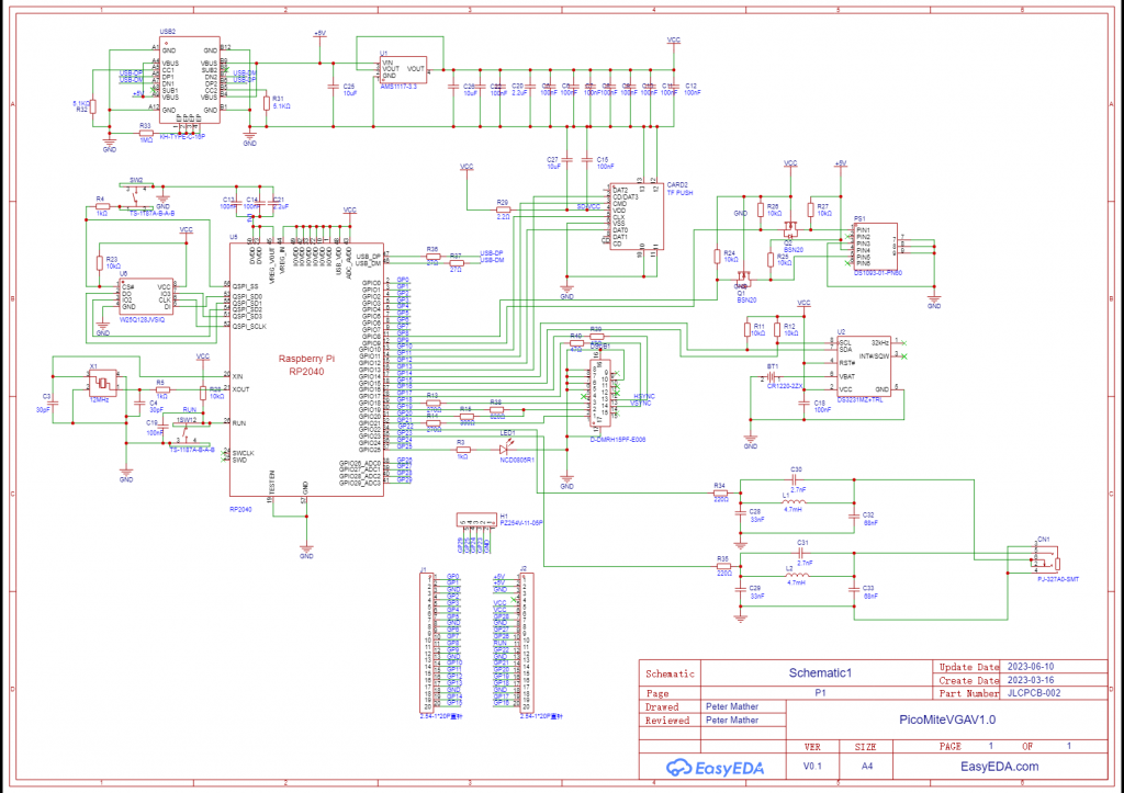 PicoMiteVGA10_scheme.pdf |
||||
| cosmic frog Guru Joined: 09/02/2012 Location: United KingdomPosts: 308 |
Thanks. I'll give it a go. Dave. |
||||
| javavi Guru Joined: 01/10/2023 Location: UkrainePosts: 565 |
PicoGAME VGA https://github.com/thwill1000/pico-game-vga 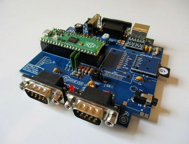 PicoGAME VGA_14A Circuit.pdf |
||||
| cosmic frog Guru Joined: 09/02/2012 Location: United KingdomPosts: 308 |
Just looked at the schematics and the wiring is the same on my board, only the sound is wired to GP0 and GP1 so my board should work ok just without sound. I will have to have another try. |
||||
| Mixtel90 Guru Joined: 05/10/2019 Location: United KingdomPosts: 8935 |
I sort of recognise that board. :) PicoGAME has GP0, GP1, GP2 and GP3 on Port A for the joystick/controller connections. Edited 2024-02-15 07:17 by Mixtel90 Mick Zilog Inside! nascom.info for Nascom & Gemini Preliminary MMBasic docs & my PCB designs |
||||
| javavi Guru Joined: 01/10/2023 Location: UkrainePosts: 565 |
Hi Mick, I did an assembly for PicoGAME VGA using a NES gamepad connected to Port A, which uses GPIO ports for its operation: GP1, GP2, GP3 PWM sound on ports GP6, GP7 If you or anyone else needs it, I can change the connection as you please. 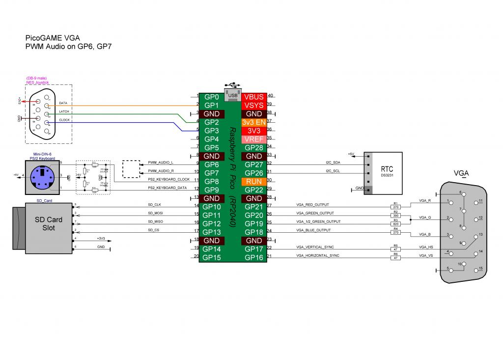 And, although the RTS is shown in this diagram, it is not used for the GameBoy emulator. Best regards to everyone, Java |
||||
| cosmic frog Guru Joined: 09/02/2012 Location: United KingdomPosts: 308 |
Thanks for the great diagram javavi, this is very useful. Would you be able to convert other consoles as well as the Gameboy on this platform? Dave. |
||||
| javavi Guru Joined: 01/10/2023 Location: UkrainePosts: 565 |
Yes, this could be done, for example Sinclair Spectrum 48k and 128k! But there is one point, I don’t know how to convey the Spectrum color palette (8 colors with two brightness levels) using the PicoMite VGA121 scheme!?? |
||||
| javavi Guru Joined: 01/10/2023 Location: UkrainePosts: 565 |
Yes, I understand from the PicoGameVGA scheme that on port A to connect the NES joystick, pins 2,3,4 are used corresponding to the GPIO ports GP1, GP2, GP3 |
||||
| Martin H. Guru Joined: 04/06/2022 Location: GermanyPosts: 1471 |
could be done , only missing Color is Bright White Spectrum Colors Scolors: 'Normal 8 Colors Data 0,255,16711680,16711935,32768,33023,16744448,16777215 'With Bright Data 0,16639,16728064,16728319,65280,65535,16776960,16777215 Normal 8 Colors R G B 00 00 00 BLACK 00 00 FF BLUE FF 00 00 RED FF 00 FF MAGENTA 00 80 00 Green 00 80 FF Cyan FF 80 00 Yellow FF FF FF WHITE With Bright on R G B 00 00 00 BLACK 00 40 FF Light BLUE FF 40 00 Light RED FF 40 FF Light MAGENTA 00 FF 00 Light Green 00 FF FF Light Cyan FF FF 00 Light Yellow FF FF FF WHITE  see : Open SCR file (ZX Spectrum standard screen) Edited 2024-02-15 23:44 by Martin H. 'no comment |
||||
| Page 1 of 3 |
|||||
| The Back Shed's forum code is written, and hosted, in Australia. | © JAQ Software 2026 |
