
|
|
Forum Index : Microcontroller and PC projects : Very weird LCD problem...
| Author | Message | ||||
Grogster Admin Group Joined: 31/12/2012 Location: New ZealandPosts: 9586 |
Thanks, Jim. I have replaced the LCD female headers, but nothing has changed. Smoke makes things work. When the smoke gets out, it stops! |
||||
| Justplayin Guru Joined: 31/01/2014 Location: United StatesPosts: 327 |
The one thing I noticed looking at the images is the GND and CS pins appear to be connected to a copper pour. Is that section of copper pour truly grounded? --Curtis I am not a Mad Scientist... It makes me happy inventing new ways to take over the world!! |
||||
bigmik Guru Joined: 20/06/2011 Location: AustraliaPosts: 2949 |
GDay Grogster, All, Check that the TFT GND pin is actually connected to GND, by adding the switch you ‘may’ have an isolated GND pour meaning that GND on the TFT is at actually system GND. It is hard to follow the traces with the colour choices but it is basically the same as the original except for the switch and different HC12 layout. Kind Regards, Mick (the big one) . Mick's uMite Stuff can be found >>> HERE (Kindly hosted by Dontronics) <<< |
||||
| Grogster Admin Group Joined: 31/12/2012 Location: New ZealandPosts: 9586 |
Good point, but yes - the LCD GND and the CS pin are connected to the common ground.  Once I unearth my DSO next week, I will try to get a screenshot of the D/C line that Jim wanted. Smoke makes things work. When the smoke gets out, it stops! |
||||
| bigmik Guru Joined: 20/06/2011 Location: AustraliaPosts: 2949 |
Hi Grogster, Looking further it does seem that a GND does connect to the Pic and the TFT but that image above is your old version without the new switch. This is a curious issue. Suggestions are to minimise it by removing sections you don’t need (like the SD connector and any HC12) Not much to minimise though. Are you able to post images of top and bottom copper without the copper pours and individual copper layers (with pours) and without the other layer showing? That would make tracing the wiring easier. Regards, Mick . Edited 2024-04-21 11:01 by bigmik Mick's uMite Stuff can be found >>> HERE (Kindly hosted by Dontronics) <<< |
||||
| bigmik Guru Joined: 20/06/2011 Location: AustraliaPosts: 2949 |
Grogster, Another thought. Are the 2 capacitors on the VReg actually 10uF? You may have accidentally used 10nf maybe? I can’t see any logical reason for one board to work and the other not to. Mick Mick's uMite Stuff can be found >>> HERE (Kindly hosted by Dontronics) <<< |
||||
| Turbo46 Guru Joined: 24/12/2017 Location: AustraliaPosts: 1638 |
I did ask about the capacitor and Grogster said it was OK. The PIC does run and drive the LEDs but I guess it could be marginal? Could be worth trying another. Bill Keep safe. Live long and prosper. |
||||
| Mixtel90 Guru Joined: 05/10/2019 Location: United KingdomPosts: 7823 |
The regulator pads look right for the SOT-223 package. I hope that's the one used here as the SOT-89 is different. Mick Zilog Inside! nascom.info for Nascom & Gemini Preliminary MMBasic docs & my PCB designs |
||||
| Grogster Admin Group Joined: 31/12/2012 Location: New ZealandPosts: 9586 |
Yes, SOT-223.  I'll upload the images Mick asked for later, but have some other work to do today, so that will be later on tonight my time. Smoke makes things work. When the smoke gets out, it stops! |
||||
| zeitfest Guru Joined: 31/07/2019 Location: AustraliaPosts: 570 |
Any resolution ? Without a deep dive my only thought is that the blue pour connections running between the 170 pins seem thin, maybe one is intermittent or high resistance. Displays can be a pain. (ed - what size is the display ? I got the impression it was 2.2 ? As it happens I have a similar display (2.2") that works OK but the controller is ILI9225.) Edited 2024-04-26 11:46 by zeitfest |
||||
| Grogster Admin Group Joined: 31/12/2012 Location: New ZealandPosts: 9586 |
No, and as it is relatively low-priority compared to other paid work I needed to get done, it has basically just sat on the bench for the last few days.  I have not forgotten it though, and will get back to it when I can - which should be sometime next week when I expect to have a little more time to tinker. LCD is an ILI9341, 2.2" without touch. Smoke makes things work. When the smoke gets out, it stops! |
||||
| Grogster Admin Group Joined: 31/12/2012 Location: New ZealandPosts: 9586 |
OK, I have this working perfectly now.   It was a SCHOOLBOY mistake - anyone wanna guess what it was, before I tell you what it was? Nothing to do with the PCB, the traces or the layout. Anyone wanna take a stab at what the problem was? Smoke makes things work. When the smoke gets out, it stops! |
||||
| Glen0 Regular Member Joined: 12/10/2014 Location: New ZealandPosts: 95 |
Something to do with the power supply? |
||||
| Turbo46 Guru Joined: 24/12/2017 Location: AustraliaPosts: 1638 |
I can only think of it being the wrong value component but the MM2 and the Microbridge work and the backlight is working. I give up. Bill Keep safe. Live long and prosper. |
||||
| Grogster Admin Group Joined: 31/12/2012 Location: New ZealandPosts: 9586 |
You win. I installed the wrong regulator!  Supposed to be MCP1703A-33(3v3), I put in a MCP1703A-50(5v) As soon as I spotted that, I had a bit of an "A-HA!" moment. Replaced the 5v regulator with the correct 3v3 regulator, and everything sprung to life - on the original pin-out etc. I took it from the static sheilded bag containing regs that SHOULD be 3v3, but I must have let one 5v slip into that bag, when I sorted them. I will now check all regs in both the 3v3 bag, and the 5v bag, so as not to run into that again! I guess I also should have been checking the part number on the reg itself, rather then just ASSUMING that every one in there, were the correct output voltage... Again, a pretty schoolboy mistake, and I should have detected that WAY before now, and everyone also knows what assumptions are the mother of...    That mistake, would have meant that the MM2 chip was firing 5v logic(or close enough to 5v) at the LCD, and I guess it upset the SPI port on the LCD module, whose I/O is 3v3 max I seem to recall. I'm probably pretty lucky that I did not kill the LCD, but it still is working fine! Probably lucky that I did not kill the 170 MM2 chip too, as it is only rated for 3.6v maximum! 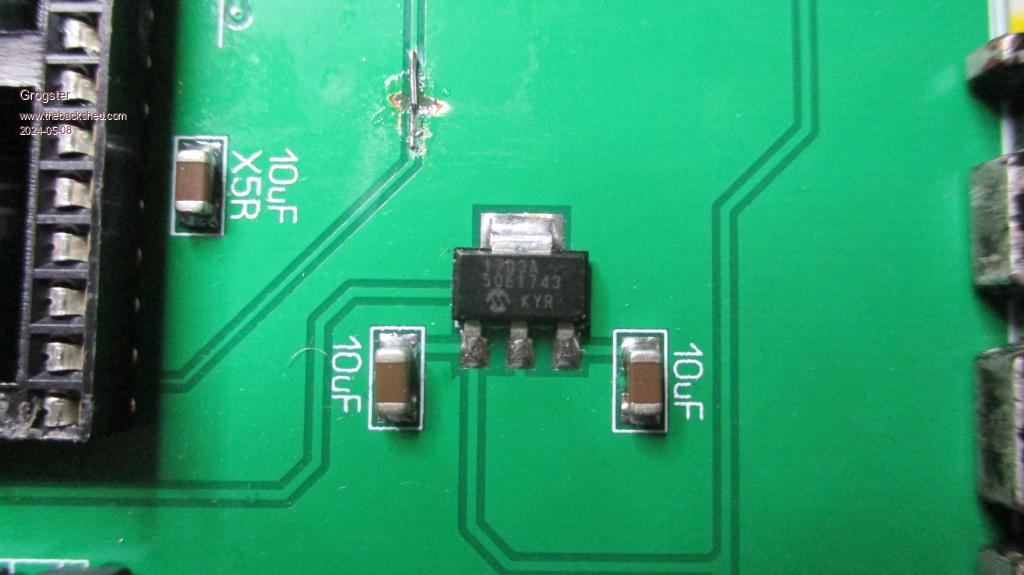 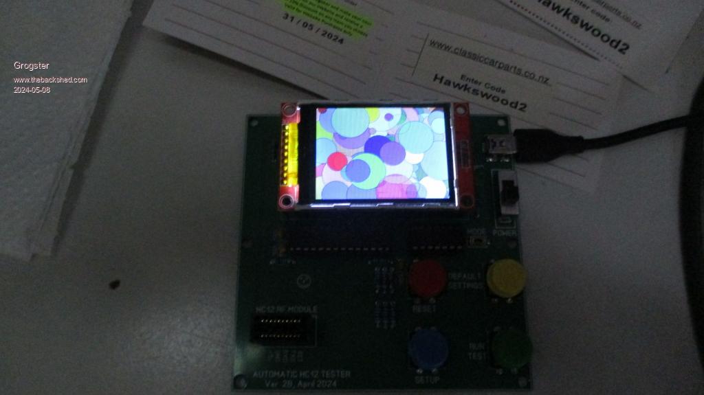 Edited 2024-05-08 13:30 by Grogster Smoke makes things work. When the smoke gets out, it stops! |
||||
| JohnS Guru Joined: 18/11/2011 Location: United KingdomPosts: 4033 |
Finding it ... persistence paid off! John |
||||
| Grogster Admin Group Joined: 31/12/2012 Location: New ZealandPosts: 9586 |
The only thing I am a bit sorry about, is starting this thread, and it taking three pages.......to find out it was my f-ing mistake all along.   I could certainly have simply NOT posted the fix - but then, that does not give the rest of you a chance to have a giggle at my expense!  Smoke makes things work. When the smoke gets out, it stops! |
||||
| Mixtel90 Guru Joined: 05/10/2019 Location: United KingdomPosts: 7823 |
It's never easy to spot your own errors, you are far too close to the design. This is something I learned while working as an electrical draughtsman. If possible you should always check each other's work. Sometimes it only needs one wrong wire number to start hours of fault finding. Mick Zilog Inside! nascom.info for Nascom & Gemini Preliminary MMBasic docs & my PCB designs |
||||
| lizby Guru Joined: 17/05/2016 Location: United StatesPosts: 3348 |
Shades of the days of program "desk-checking" by a group (in a period when a new compilation required because of a typo might mean a 4-hour turnaround time). But is there a single one of us active on this thread who has another shedder available to look at physical parts? Having a worldwide group is great for solving software problems or design problems, but more limited when the solution is to look at a part with a magnifying glass (while knowing what you are looking at and why). Congrats on finding the solution--and for sharing. PicoMite, Armmite F4, SensorKits, MMBasic Hardware, Games, etc. on fruitoftheshed |
||||
| Volhout Guru Joined: 05/03/2018 Location: NetherlandsPosts: 5030 |
Grogster, You can always say that the box with 1703 regulators also fell on the floor, at the same time the 10-100-1k resistors fell... Volhout PicomiteVGA PETSCII ROBOTS |
||||
| The Back Shed's forum code is written, and hosted, in Australia. | © JAQ Software 2025 |
