
|
|
Forum Index : Microcontroller and PC projects : PiciMite RP2350 + PSRAM 8M
| Author | Message | ||||
| javavi Guru Joined: 01/10/2023 Location: UkrainePosts: 569 |
Today I received a parcel with RP2350-Plus and immediately soldered another PSRAM chip on top of the flash memory chip installed on the board. I have this chip ESP-PSRAM64H I also soldered the PSRAM chip selection control pin to the GP8 port for my circuit. 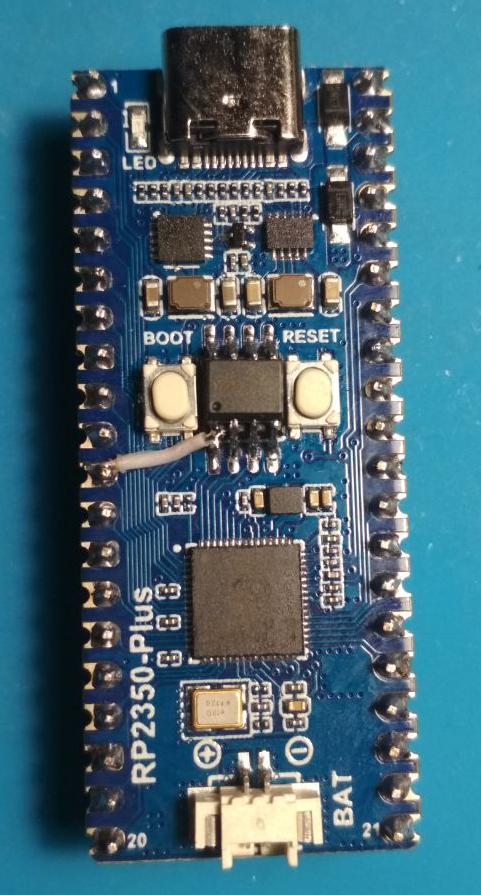 The initial welcome screen and the MEMORY command say that all PSRAM memory is available to the user. 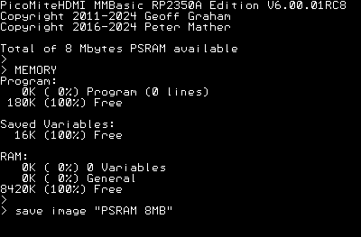 Now my question is, is there a stress test to test the entire volume of this PSRAM chip, as well as tests for memory access speed?? |
||||
| dddns Guru Joined: 20/09/2024 Location: GermanyPosts: 891 |
Hello Javavi! nice clean hack even with the jumper you are using now. Two questions: Is pin 1 of the ESP-PSRAM64H only connected to gp8 or is it as well soldered to pin1 of the chip below? Does the psram expand the heap memory? I would like to create a framebuffer with a 800x480 display. Edited 2024-12-22 19:01 by dddns |
||||
| javavi Guru Joined: 01/10/2023 Location: UkrainePosts: 569 |
Hi dddns! 1) Yes, the "Pico2" port pin of the GP8 is connected to pin 1 of the PSRAM chip (ESP-PSRAM64N). Later, I improved this life hack with a jumper that disconnects the line from the GP8 and a pull-up resistor for the CS pin on the PSRAM chip. So that it could be disconnected and connected when needed. 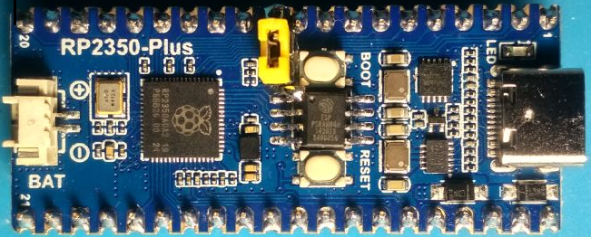 Other Pico2 clones with flash memory in a large case have appeared on AliExpress, to which you can solder a PSRAM microcircuit on top in a similar way. 2) OPTION PSRAM PIN GP8 Expands the available RAM heap up to 8 Megabytes. So far I'm only testing this on PicoMite variants with VGA and HDMI video outputs. |
||||
| javavi Guru Joined: 01/10/2023 Location: UkrainePosts: 569 |
Option default integer SBK=1 TEST_BEGIN: SBW=SBK*128 SOURCE=&h5555555555555555:DEST=0 NB=((MM.Info(heap)\1024)-5)\SBK Dim integer HEAP(NB,SBW) Print "NUMBER OF MEMORY BLOKS:";NB Print "RAM MEMORY BLOCK SIZE :";SBK*1024,"byte" Print "TOTAL SIZE TESTING RAM:";NB*SBK,"Kbyte" Print "----------------------|------|-------" Timer =0 For i=0 To SBW-1 HEAP(0,i)=SOURCE Next : Print Timer;"mS","-- Time to wtite 1 Block RAM" Timer =0 For i=0 To SBW-1 For n=0 To NB-1 HEAP(n,i)=SOURCE Next : Next : Print Timer;"mS","-- All RAM Fill Time" Timer =0 For i=0 To SBW-1 DEST=HEAP(0,i) Next : Print Timer;"mS","-- Time to read 1 Block RAM" Timer =0 For i=0 To SBW-1 For n=0 To NB-1 DEST=HEAP(n,i) Next : Next : Print Timer;"mS","-- All RAM Read Time" Timer =0:n=NB-1 For i=0 To SBW-1 HEAP(0,i)=HEAP(n,i) Next : Print Timer;"mS","-- Time to Copy 1 Block RAM" Timer =0 For n=0 To NB-2 For i=0 To SBW-1 HEAP(n,i)=HEAP(n+1,i) Next : Next : Print Timer;"mS","-- All RAM Copy Time" Clear Input "Enter RAM BLOCK SIZE in Kbyte: ",SBK If SBK>0 Then CLS :GoTo TEST_BEGIN End |
||||
| dddns Guru Joined: 20/09/2024 Location: GermanyPosts: 891 |
Does this hack also work with a RP2040? |
||||
| javavi Guru Joined: 01/10/2023 Location: UkrainePosts: 569 |
Unfortunately, no! This is exclusively a feature of the new RP2350 chip. Which hardware supports the operation of two devices on the QMI bus |
||||
| javavi Guru Joined: 01/10/2023 Location: UkrainePosts: 569 |
"Black Pico2" from WeAct RP2350A-V10 or V20 is also suitable for soldering the PSRAM memory chip on top and is not expensive. 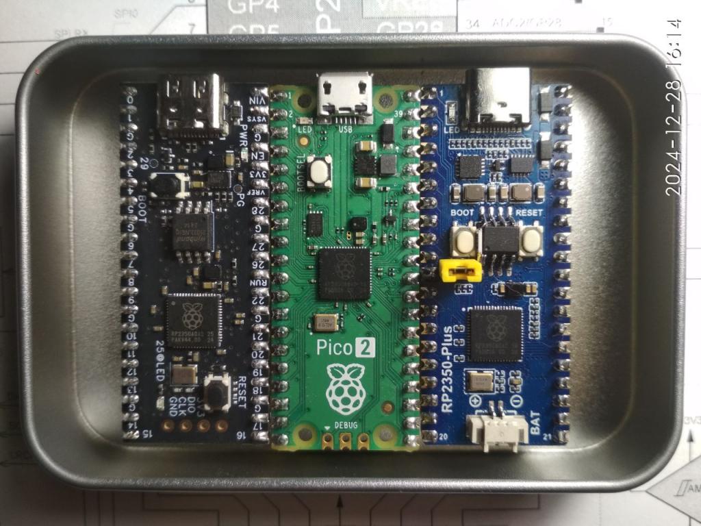 https://www.aliexpress.com/item/32778272059.html https://www.aliexpress.com/item/1005008142140656.html |
||||
mclout999 Guru Joined: 05/07/2020 Location: United StatesPosts: 512 |
I have an HDMIUSB main board system with stock PICO 2 and would like to get this ram option on that. Is that possible? That board needs some solder points on the bottom of the PICO 2 so that seems to be an issue. Is there anyone who could make a new board with a socket for the PICO 2 instead of using the Tessellated points? They call me Shai-Hulud (The maker) |
||||
| javavi Guru Joined: 01/10/2023 Location: UkrainePosts: 569 |
I think that with desire and due skill everything is possible!  You can solder a PBS connector to the board pads and put a Pico2 module with soldered PLS pins on it. These Pico2 clones also have USB line pads at the bottom, but they do not match the original Pico2 board. Therefore, you can solder wires to them or take them from the USB Type-C connector itself (as shown in the photo) 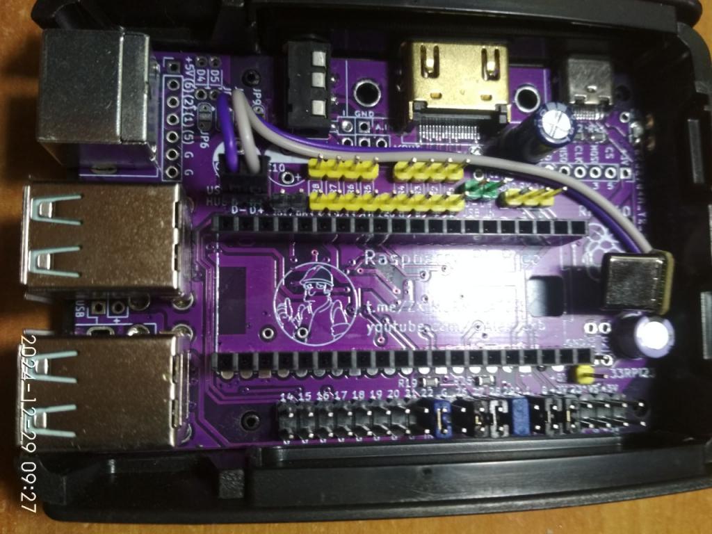 |
||||
| The Back Shed's forum code is written, and hosted, in Australia. | © JAQ Software 2026 |
