
|
|
Forum Index : Microcontroller and PC projects : I've found an interesting module for I2C
| Page 1 of 2 |
|||||
| Author | Message | ||||
| Mixtel90 Guru Joined: 05/10/2019 Location: United KingdomPosts: 8904 |
TCA9548A Modules are very cheap on AE. Basically, it splits a single I2C port into eight. You send it the board's address and the number of the port you want access to. It then connects the ports together until a different one is selected. It's more than that though. All the ports are open drain (like they should be) so you can add your own pullups. So you can have a mixture of 5V and 3V3 I2C ports. The module can be powered from 1V8 to 5V and the level shifting is automatic and invisible, just connect the input port pullups to your system voltage. Looks interesting, I might get one to play with. Mick Zilog Inside! nascom.info for Nascom & Gemini Preliminary MMBasic docs & my PCB designs |
||||
| stanleyella Guru Joined: 25/06/2022 Location: United KingdomPosts: 2807 |
https://www.ebay.co.uk/itm/335701328995 why do we need it when you can connect multiple i2c anyway? |
||||
| Mixtel90 Guru Joined: 05/10/2019 Location: United KingdomPosts: 8904 |
You can only connect multiple devices if they all have different addresses. The WII game controllers only have one or possibly two addresses. If you want three on the same machine (as on the later CMM2) you can't unless you have three I2C ports. Using this module you could have eight on a single I2C port of a Pico. And another eight on the other. :) Note that you could also, if you level shift to get the I2C connection up to 5V from the Pico, mix 5V, 3.3V and 1.8V I2C devices on the eight I2C lines. I don't think it supports 3V3 output with 3V3 input, unfortunately, I think you have to level shift. I'm still investigating the data sheet. Oh, and you can get five for that price on AE. :) Mick Zilog Inside! nascom.info for Nascom & Gemini Preliminary MMBasic docs & my PCB designs |
||||
| Volhout Guru Joined: 05/03/2018 Location: NetherlandsPosts: 5930 |
Yes that works. 3v3 in and 3v3 out in any mix. We use them with I2C devices a lot. Specifically those that have a default I2C address that can be re-programmed in sw. We always keep them on default since there is no surprise if you ever need to replace one. Example: the melexis thermal cameras, like MLX90614. Volhou PicomiteVGA PETSCII ROBOTS |
||||
| PhenixRising Guru Joined: 07/11/2023 Location: United KingdomPosts: 1954 |
Is there such an animal for UART? |
||||
| PhenixRising Guru Joined: 07/11/2023 Location: United KingdomPosts: 1954 |
I found this and they are $7 at LCSC (has buffers) |
||||
| stanleyella Guru Joined: 25/06/2022 Location: United KingdomPosts: 2807 |
I ordered a TCA9548A. I will probably ask for help cos don't use i2c much. V53L0X, MCP23017, ssd1306 |
||||
| Mixtel90 Guru Joined: 05/10/2019 Location: United KingdomPosts: 8904 |
The info for using I2C is in the manual, Appendix B, and it's pretty good! It's not much more difficult than using a COM port. The main thing is that it's up to you to create the protocol that you want for a particular job. The module is easy to work with. If the address pins are all grounded it's address is &h70 The individual channels are then &h0 to &h7 so you send &H70 for the first, &h71 for the second, &h72 for the third etc. There are no other registers in it. Once you have selected the channel like that you just use the I2C as normal to talk to the device that you want. I found that, for me, the best way to play was to use two Picomites as master and slave. Set the slave up to print whatever it gets over I2C then send it stuff from the master. That way you have full control over setting the number of bytes sent and received and how they are handled - and how the 7-bit addressing system works! . Mick Zilog Inside! nascom.info for Nascom & Gemini Preliminary MMBasic docs & my PCB designs |
||||
| stanleyella Guru Joined: 25/06/2022 Location: United KingdomPosts: 2807 |
dunno if a0 to a2 are hardwired or go to gp pins. 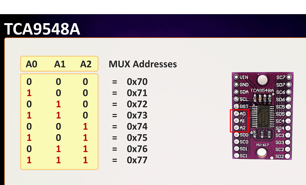 |
||||
| Volhout Guru Joined: 05/03/2018 Location: NetherlandsPosts: 5930 |
Easy, connect the module to your desired I2C bus, and run an I2C scan. From the address found you know the wiring. Volhout PicomiteVGA PETSCII ROBOTS |
||||
| stanleyella Guru Joined: 25/06/2022 Location: United KingdomPosts: 2807 |
this is just the devices i2c addresses itself which can be 0x70 to 0x77. mines in the post. solder it up and post |
||||
| stanleyella Guru Joined: 25/06/2022 Location: United KingdomPosts: 2807 |
I don't get this. the tca has address so writing 2 bytes to it to set up a device and the register so what channel conected to for each device 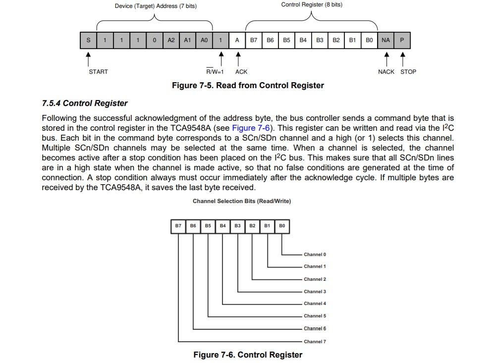 |
||||
| Mixtel90 Guru Joined: 05/10/2019 Location: United KingdomPosts: 8904 |
It's easy enough. You are sending one byte (B7-B0) to the address of the TCA. The TCA address is [0]1110[A2][A1][A0] - that's 70 to 77 depending on the address pins. The next bit is 0 to read from it or 1 to write to it. You are selecting a device, so this will be a 1 so that you can write to the device select strobe. The next 8 bits after the ACK (which is automatic) are the device strobes, one per I2C port. So a 1 on B0 will select port 0, a 1 on B1 will select port 1 etc. All non-used ports have their strobes set to 0. It's possible to select two I2C ports at the same time (not sensible for many devices) by setting both their strobe bits high. . Edited 2025-08-01 07:23 by Mixtel90 Mick Zilog Inside! nascom.info for Nascom & Gemini Preliminary MMBasic docs & my PCB designs |
||||
| stanleyella Guru Joined: 25/06/2022 Location: United KingdomPosts: 2807 |
thanks Mick. wish I hadn't bought it. thought it was pointless unless connecting devices with same address. |
||||
| Volhout Guru Joined: 05/03/2018 Location: NetherlandsPosts: 5930 |
It also level shifts. If you have 5v serial lcd or pcf8574 io expanders this is usefull. Volhout PicomiteVGA PETSCII ROBOTS |
||||
| Mixtel90 Guru Joined: 05/10/2019 Location: United KingdomPosts: 8904 |
That's what it's intended for. Of course, it doesn't care what the addresses of the I2C devices are. You can also mix 3V3 and 5V I2C devices without any level shifters - the Pico sees them all as 3V3. Confusingly, there are two "standards" (Qwiic and Stemma QT) that use I2C on the same 1mm pitch JST connector but with different coloured wires. One is 3V3 and the other is 5V. Using one of these modules and a link system would let you mix and match any of either sort of module. :) . Edited 2025-08-02 07:10 by Mixtel90 Mick Zilog Inside! nascom.info for Nascom & Gemini Preliminary MMBasic docs & my PCB designs |
||||
| stanleyella Guru Joined: 25/06/2022 Location: United KingdomPosts: 2807 |
another impulse buy after recommendations, like waveshare devices. seemed a good idea at the time. I got to rationalise what I want to do |
||||
| Mixtel90 Guru Joined: 05/10/2019 Location: United KingdomPosts: 8904 |
I suppose you might be able to do other things with these. Use I2C to select a channel SETPIN the pins Use them as CLK and DATA to read or write a shift register SETPIN ht e pins back to I2C Select another channel So you could have 8 shift registers on two pins. Mick Zilog Inside! nascom.info for Nascom & Gemini Preliminary MMBasic docs & my PCB designs |
||||
| stanleyella Guru Joined: 25/06/2022 Location: United KingdomPosts: 2807 |
I not knocking the device but admit I don't use i2c. all were experimental and the 16 channel gpio was great but who else got one and the laser rangefinder was brill connected to i2c oled. no mux needed. got so far and lost interest with device 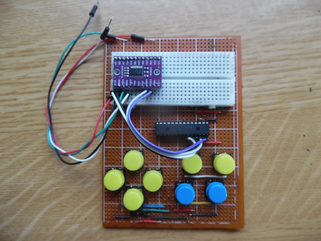 |
||||
| stanleyella Guru Joined: 25/06/2022 Location: United KingdomPosts: 2807 |
this has 16 io and you could have 8 devices and you can have 8 tca so (16*8)*8=1024 io for whatever  |
||||
| Page 1 of 2 |
|||||
| The Back Shed's forum code is written, and hosted, in Australia. | © JAQ Software 2026 |
