
|
|
Forum Index : Microcontroller and PC projects : GAP1 - more evolution of the PicoGAME
| Page 1 of 2 |
|||||
| Author | Message | ||||
| Mixtel90 Guru Joined: 05/10/2019 Location: United KingdomPosts: 8904 |
Sometimes I design something just for the pure joy of it. This is one of those. It's unashamedly a gaming machine - probably as close to the CMM2 as I can get using the Pico too. It is intended to be fitted into the Hammond square, translucent blue case so it even has flashy lights to play with. :) It's pushed along by the PGA2350 module, so you have PSRAM available. Neither GP0 nor GP47 are used so if you have a module that's been modified for GP0 it can still be used. 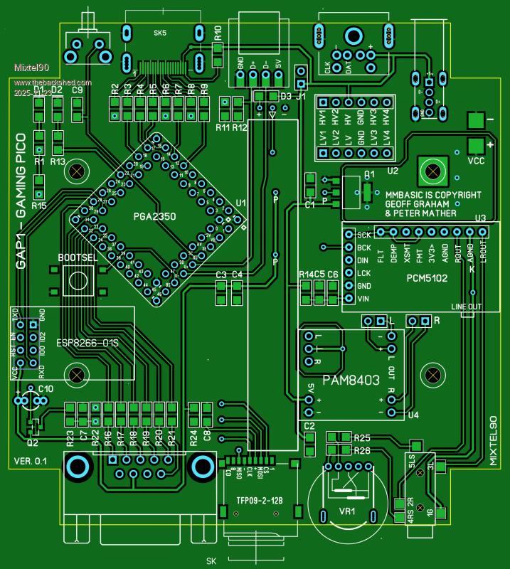 I decided to forget USB, to remove a processing layer, and use a PS2 keyboard and mouse. It also saves a chunk of PCB area. The downside is that you can't use USB controllers. I also sacrificed the RTC as it needs an I2C port that I can't spare. However, there is space for a ESP8266-01S so you could set the time from a time server. The game port is very flexible though. This has every data pin reconfigurable in software. My idea is that at boot you can choose which controller you want to use by default and a library routine will set it up for you (it can also be reconfigured by your program). The port can also be used as 7 GPIO pins, GP46 has 100nF to GND though. You can choose: Atari joystick on GP40,41,42,43 and fire on GP46 NES/SNES on GP41,42,43 As all inputs can be ADC you could use an X-Y analogue stick with several buttons Both I2C ports on GP42,43 (I2C2) and GP44,45 (I2C) - both 3V3 I'm still undecided about audio. At the moment I envisage stereo down-firing speakers or fixed level line output via the jack socket. However I prefer headphones personally and I'm considering scrapping the line output and using speakers or headphones (via a better quality headphone amp). It's I2S anyway. A strip of four programmable LEDs is there just for the hell of it and to light the box up. :) I decided that I was going to use surface mount components where reasonably possible. That's so I can try building it on a hotplate! However, it's all 1206 (apart from a mosfet and the regulator) so quite easily hand solderable. I think it's one of my better-looking designs so far. :) Mick Zilog Inside! nascom.info for Nascom & Gemini Preliminary MMBasic docs & my PCB designs |
||||
| Mixtel90 Guru Joined: 05/10/2019 Location: United KingdomPosts: 8904 |
No, it's not disappeared. :) There's been a lot of work done. I'm finally building the prototype but waiting for a few components. I've also done most of the manual now. 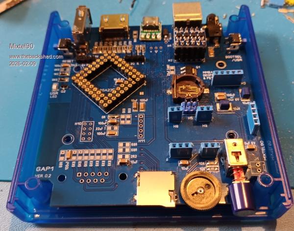 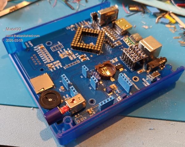 There's a power switch. :) I solved the audio problem. By default it has a fixed level line output on the rear and also drives a pair of little internal speakers. It's possible to disconnect these to use external passive speakers. It should also be possible to fit a headphone jack, but this option hasn't been tested yet. There is also an option for a RTC with replaceable backup battery now. Bootsel and Reset are both accessible from outside the case now. Mick Zilog Inside! nascom.info for Nascom & Gemini Preliminary MMBasic docs & my PCB designs |
||||
| Mixtel90 Guru Joined: 05/10/2019 Location: United KingdomPosts: 8904 |
:( PROJECT ABANDONED My PGA2350 won't overclock above 200MHz At 250MHz it won't boot at all. Whether later ones are any better I don't know, but the current ones are still the original A2 stepping. Whether they are faster though I've no way of knowing without buying one to try and getting stuck with another one that doesn't work. Currently HDMI on a RP2350B-based module is only a dream for me. :( Mick Zilog Inside! nascom.info for Nascom & Gemini Preliminary MMBasic docs & my PCB designs |
||||
| Volhout Guru Joined: 05/03/2018 Location: NetherlandsPosts: 5930 |
That is bad Mick, All this work, and then this set back. The problem is most likely in the core voltage, being to low. That may be why Peter pulled the core voltage regulator external. Overclocking is an art... Volhout Edited 2026-02-11 20:49 by Volhout PicomiteVGA PETSCII ROBOTS |
||||
| matherp Guru Joined: 11/12/2012 Location: United KingdomPosts: 11499 |
Are you overloading the 3.3V supply from the PGA2350? I'm running them at 360MHz with no issue in the PalmPico |
||||
| dddns Guru Joined: 20/09/2024 Location: GermanyPosts: 841 |
I've seen this behavior with mine too. That's why I don't touch the 3v3 from the PGA at all. |
||||
| Mixtel90 Guru Joined: 05/10/2019 Location: United KingdomPosts: 8904 |
The 3V3 is from an external regulator and has decoupling close to the module. The on-board regulator is disabled. The Pico is the only device on the supply. The only thing missing is 22uF Tantalum next to the regulator. I have some on order but they are in 2nd class post so could take a week or two. Mick Zilog Inside! nascom.info for Nascom & Gemini Preliminary MMBasic docs & my PCB designs |
||||
| dddns Guru Joined: 20/09/2024 Location: GermanyPosts: 841 |
I think to separate the the 3V3 is the best. Why don't you want to use the internal regulator for the core? To find out it would make sense to test the PGA isolated.. |
||||
| Mixtel90 Guru Joined: 05/10/2019 Location: United KingdomPosts: 8904 |
I've got the board set up as it's going to be used eventually, with a ESP8266-01S and RTC. That needs a lot of current, which the on-board reg couldn't supply. Also, 3V3 will be wired out to the controller port. However, I could take the external reg off, I suppose, and re-enable the on-board one for testing. I could probably disable the PSRAM select signal too, but that shouldn't be doing anything by default. Mick Zilog Inside! nascom.info for Nascom & Gemini Preliminary MMBasic docs & my PCB designs |
||||
| dddns Guru Joined: 20/09/2024 Location: GermanyPosts: 841 |
I thought de-soldering the pins 3V3en and 3V3 on the PGA might be all there is to do.. |
||||
| Mixtel90 Guru Joined: 05/10/2019 Location: United KingdomPosts: 8904 |
Well, yeah. But the trace layout is working against me - I can't simply unsolder the 3V3 pin. I'm transferring the module onto a simple test board which has no external reg or display components. It'll do for the moment. First I have to get rid of the dratted CYD module that's in the way... EDIT: Now using the test board. It has booted and options show a 250MHz cpu speed. However, FILES causes it to lock up. I suspect a slow flash chip has been used on early versions, but how you can tell I've no idea. And now Win11 has gone into a sulk and won't let it reconnect. Of course. :( . Edited 2026-02-11 23:38 by Mixtel90 Mick Zilog Inside! nascom.info for Nascom & Gemini Preliminary MMBasic docs & my PCB designs |
||||
| Mixtel90 Guru Joined: 05/10/2019 Location: United KingdomPosts: 8904 |
Sod this. Windows is even refusing to see the virtual drive after a complete power off and reboot. I think I'll do something else. Mick Zilog Inside! nascom.info for Nascom & Gemini Preliminary MMBasic docs & my PCB designs |
||||
| Mixtel90 Guru Joined: 05/10/2019 Location: United KingdomPosts: 8904 |
I decided to bite the bullet and get a couple more from Pimoroni while they have the A2 ones at half price. I don't need the IO fix for this project and there are no later stepping versions available anyway. They are nice little modules and I'll find a use for them eventually. I have a project in mind to use one to drive a parallel mode LCD at some point. Mick Zilog Inside! nascom.info for Nascom & Gemini Preliminary MMBasic docs & my PCB designs |
||||
| PhenixRising Guru Joined: 07/11/2023 Location: United KingdomPosts: 1954 |
Mick, I had this issue of the module not being recognised no matter what but I found a fix. I need to think back. I remember suspecting that the module was bricked but it wasn't. Need to hit the sack and hopefully I'll remember tomorrow. |
||||
| Mixtel90 Guru Joined: 05/10/2019 Location: United KingdomPosts: 8904 |
This is "fun". I got it to run 6.00 at 150MHz. Now I have it running 6.00.03 (from the zip named 6.01.03) and the heartbeat is running fine. The 6.02.00 won't run at all, even after nuking the flash. These are all the same basic version. It's pointless attempting the HDMI files and there's no USB on this board. Windows behaves slightly better if you remember to disconnect from Tera Term and shut it down before messing about, otherwise it's power the PC off for a min or two before trying again! Mick Zilog Inside! nascom.info for Nascom & Gemini Preliminary MMBasic docs & my PCB designs |
||||
| Mixtel90 Guru Joined: 05/10/2019 Location: United KingdomPosts: 8904 |
I might be back on track now. :) Plugged in a brand new PGA2350, loaded the HDMI version of the firmware and it booted. HDMI is working now (at 640x480 anyway) and so is the SD card after realizing that you can't set system SPI on this... Doh! Still quite a bit to do, but at least there's hope now. :) My missing resistors and tantalum caps have turned up too. EDIT: Oh yes.... :) The PS2 keyboard, audio side and LED strip are working. The controller port was part tested yesterday. The tiny little speakers sound awful, but should be a bit better when cased as what little bass they can produce is totally lost without a baffle of some sort. EDIT: And now the ESP8266-01S can be used via COM1. I have a crude terminal program running and I've got it to say something other than "ERROR" so things are looking up. I'm working on a custom Library for this board to support configuring the controller port and, hopefully, the ESP (if I can figure out how to use it!). Edited 2026-02-14 06:18 by Mixtel90 Mick Zilog Inside! nascom.info for Nascom & Gemini Preliminary MMBasic docs & my PCB designs |
||||
| lizby Guru Joined: 17/05/2016 Location: United StatesPosts: 3782 |
How did you manage to solder the HDMI connector? And it looks like you have only 5 pins connected from the PR2350 (or do the vias indicate 8). How does that work? ~ Edited 2026-02-17 11:03 by lizby PicoMite, Armmite F4, SensorKits, MMBasic Hardware, Games, etc. on FOTS |
||||
| Mixtel90 Guru Joined: 05/10/2019 Location: United KingdomPosts: 8904 |
HDMI connector. I have a macro for SL6 to get the slots and pads positioned. I mix some solder paste with flux to make it gloopy and, using a toothpick, blob it onto the data pads. You don't need to be too accurate as the solder will flow to the right position later. Then I put some flux under the pads of the connector and put it onto the board. Now I use normal solder to solder down at least two of the fixing lugs - one first to just check that the data pins are aligned. Now, using a pointed bit on the iron, I stroke the pins of the connector out onto the pads. Iron temp is around 300C for 185C solder paste. Just work along the row like that. Then I do a continuity test on every pin to check for open or shorts. Any excess solder (and there won't be much) is easily mopped away with some narrow solder braid. usually just reheating in the area of an open circuit pin will fix that, if not then just add another bit of gloop and heat. The gloop method works nicely on just about all surface mount components. I tried it on a hotplate but I really need some lower melting point paste as some of the joints weren't good - the plate only reaches 250C. All the HDMI signals are there but through vias in some cases. The vias are actually through the pads of some of the resistors so not too visible. :) The HDMI side is working well, and did so first time, which was rather encouraging! . Edited 2026-02-17 18:11 by Mixtel90 Mick Zilog Inside! nascom.info for Nascom & Gemini Preliminary MMBasic docs & my PCB designs |
||||
| lizby Guru Joined: 17/05/2016 Location: United StatesPosts: 3782 |
Thanks. Daunting solder work for me, though. I've decided to first try this: HDMI breakout  How do you handle EID (and any other pins you find necessary). PicoMite, Armmite F4, SensorKits, MMBasic Hardware, Games, etc. on FOTS |
||||
| Mixtel90 Guru Joined: 05/10/2019 Location: United KingdomPosts: 8904 |
I don't. I connect pin 18 (5V power) to 5V and pin 19 (hot plug detect) to 5V via a resistor. Something in the region of 4K7 to 10K works. Possibly others. :) MMBasic doesn't support anything other than a very basic DVI interface. EDID is used for exchanging data about screen resolution but we can't really use it. Don't forget the series resistors with that breakout board. The Adafruit module is smaller and includes them, but it's more expensive obviously. :) I know that soldering technique sounds daunting but, honestly, it's not that bad. At first I had all sorts of problems soldering them. Pins shorted by blobs - some underneath where I couldn't fix them, melting the housing with the soldering iron, fighting with a hot air gun, all sorts. I've slowly refined it to this. I got the idea of mixing solder paste with flux from a bloke on youtube. It was about how to solder SMD stuff without a stencil. I just applied it to HDMI connectors. :) Mick Zilog Inside! nascom.info for Nascom & Gemini Preliminary MMBasic docs & my PCB designs |
||||
| Page 1 of 2 |
|||||
| The Back Shed's forum code is written, and hosted, in Australia. | © JAQ Software 2026 |
