
|
|
Forum Index : Electronics : Diversion/ dump load options (re-purpose)
| Author | Message | ||||
Downwind Guru Joined: 09/09/2009 Location: AustraliaPosts: 2333 |
Only problem is its an AC s/state relay and Karl needs the DC s/state version of it. Look a little more as there is DC ones normally listed as well. They are normally rated to around 30v on the input (coil) but again a limiting series resistor will fix this for 48 volt operation. Pete. Sometimes it just works |
||||
| VK4AYQ Guru Joined: 02/12/2009 Location: AustraliaPosts: 2539 |
Hi Pete I thought Karl could use it before the caps on the AC ouyput of the Alternator rather than stressing all the later circuitry with hi amps / volts let me know if that dosent work as that is what I am doing on one of mine. Also the DC ones are more expensive upsets my Scots blood, If he wants DC he could use a big Fet &5 volt at 200 amp for $5.00 and a bit af ally for a heat sink. All the best Bob Foolin Around |
||||
| VK4AYQ Guru Joined: 02/12/2009 Location: AustraliaPosts: 2539 |
Solid State Relays SSR 24-480V AC, 25A + Heat Sink for Solid State Relay SSR 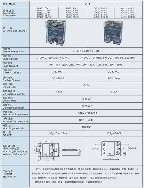
Hi Karl and Pete, Details of the relays AC an DC Bob Foolin Around |
||||
| Downwind Guru Joined: 09/09/2009 Location: AustraliaPosts: 2333 |
Bob I cant see any reason yours wont work but from my understanding Karl has a 2 wire 100m dc run from his mill to the battery and to use control on the ac side he would need to run control wires from inverter to the mill. Now do you want to tell him he needs to dig up the cable and add a couple of control wires???? (best not i think) Thinking about his setup now it could have been a worthwhile investment to run some cat 5 cable from mill to batterys in the trench, then this could be used as a control line as well as a data line for things like rpm and wind speed at the mill etc. He will proberly get cross with me for saying that now!! Pete. Sometimes it just works |
||||
| GWatPE Senior Member Joined: 01/09/2006 Location: AustraliaPosts: 2127 |
If you intend using SSRelays, then take care with the inputs. I use only 5V logic, but is you want to use 48V levels, then use a series resistor and a protection zener of say 24V across the SSRelay input. I have found that the relays with 240VAC coil work OK at 58-65VDC. The telecomunications use 48V components. Industrial switchgear normally uses 24V. Gordon. PS: any overvoltage protection components could be close to the mill. There will be power available from the main battery through wiring, or if diode blocked, when the windmill is producing power. become more energy aware |
||||
| Downwind Guru Joined: 09/09/2009 Location: AustraliaPosts: 2333 |
Gordon All very true but how do Karl get from the output of his inverter or controller back to the mill to operate control gear there?? He needs to be able to work with what he has in place not what we all think he should perhaps have. From what i understand his only real choice is to dump on the dc side at the batteries where all his control gear is. Wireless would be an option but i would not trust it as my main line of defence for control. It is ok for data as if you get a glitch it dont really matter. Pete. Sometimes it just works |
||||
| VK4AYQ Guru Joined: 02/12/2009 Location: AustraliaPosts: 2539 |
Hi Pete I see what you mean but would like to see the load at the mill to avoid cable heating, I think it would be possible to superimpose a small HF ac signal control on one of the lines and pull it of at the mill to work the relays as they only requira a small signal to control them, this is the way power companies control load balance on off peak devices. A small battery and picaxe controler would make a good project if someone can work out how the things work. Ha Ha/ All the best Bob Foolin Around |
||||
| Downwind Guru Joined: 09/09/2009 Location: AustraliaPosts: 2333 |
Bob I considered that but just another thing to give a problem and the longer you read this forum the more you get the picture of keep load diversion as simple as possiable is the best way to go. As for cable heating it is no worse than sinking lots of amps into the batteries or the grid anyway. Same Shh--stuff.....different shovel. Pete. Sometimes it just works |
||||
KarlJ Guru Joined: 19/05/2008 Location: AustraliaPosts: 1178 |
Cable loss at full load is "only" about 80W at 1.2KW 16mm2 copper I can live with that its also double the recommended minimum size per otherpower for a 300' run. I did consider running cat 5 in the conduit for the APRS world anemometer but figured I could run it at the mill end, but as you say too late now, was hard enough getting the 2 strands of 16mm2 up the 4m lengths (1" conduit) let alone the full 80m in one hit, so additions now are out of the question Running the PL20 at the mill end probably wouldnt work as under no load it would see batt voltage as it is and with full mill power going down the line there would be 4-5V difference end to end. Simplest method may be to actively cool the dump load with a couple (4x12V) of PC fans, this would keep the resistance rise to a lesser level. I dont want to get complacent with the batts as obviously there are hazards associated with overcharging them -smoke getting out! I guess the grid only needs to go down once for a windy day and what starts as a 20A load will decrease to a 15A load 15x60= 900W + 80W in the cable..... with 1KW+output 100 or so watts /8cells =12W charge even at double that can we see anything radical happening here? Perhaps back the mill off a little and go for the 80Sstar and 100delta combo rather than the 100Star/100Delta combo I have on now, this would knock 100odd watts out of the peak power and make for better low wind performance to boot Good to see there is still heaps of life in this thread Luck favours the well prepared |
||||
| VK4AYQ Guru Joined: 02/12/2009 Location: AustraliaPosts: 2539 |
Hi all How about a lo tech solution a 3 pole knife switch and a wind paddle to pul it in in high winds just keep the cows away from it, I used this method to load control a VSWM switchimg in more coils as the wind increased/ All the best Bob Foolin Around |
||||
| Downwind Guru Joined: 09/09/2009 Location: AustraliaPosts: 2333 |
Karl I have always been a fan of a two stage dump system. Stage 1 (S1) is as you intend to set your system up now and will preform as the main dump on 99% of the time. Stage 2 (S2)is just there as a backup. S2 would be set to cutin 0.5 - 1 volt higher than S1. In theory S2 would not be used unless the voltage rose above its cutin point. Meaning S1 could not handle the watts being generated or S1 had a problem. As the dump is your last line of defence between your mill holding together and it self destructing i think it makes good sense to have a 100% redundancy in your dump system You guys go to a lot of trouble and exspence to build a mill and in my opionion cut a corner with the dump system. A simple little circuit to monitor battery voltage and a extra resistive load is all thats needed for a back up. You could use the barb wire fence for a load if need be. As your above calc's show there is the risk of overloading your mill or underloading it in high wind forces. S2 can cut in and out as needed and S1 can maintain the base load as normal. Just my 20c worth. Pete. Sometimes it just works |
||||
| KarlJ Guru Joined: 19/05/2008 Location: AustraliaPosts: 1178 |
any suggestions for the circuit? A little reluctant to spend another $300 for another PL20 although its the obvious choice. My less expensive / more relaible system than the TC 48 just got less reliable and more expensive! 
Will it furl if I simply disconnect the mill from the load? Luck favours the well prepared |
||||
| Downwind Guru Joined: 09/09/2009 Location: AustraliaPosts: 2333 |
Karl, As for the circuit a simple 08m picaxe will do the monitoring and switch the relay to the second or third or forth dump as you wish. Its the beauty of these little buggers they can do whatever you program them to do. Some time back i designed and built a circuit that would switch any excess load through to a 240v electric heater using the inverter as a dump. This same circuit would work with a standard dump and would just need the triac swapped out for a solid state relay to switch the dc load to the dump. I never costed it out but would be about 1/10 of your present investment of a controller, plus the SS relay. I would still use your present controller as the main dump system and add the picaxe as a backup system. Funny Ha! i had a few blank boards for this controller made here and gave them away recently. (like 2 wks ago) Pete. Edit:- The circuit used pwm to control the dump load so not to drop the battery voltage below full capacity but this can be disabled in the program to just cutin at a given point and cut out at a lower given point. Its just program the hardware stays the same. Sometimes it just works |
||||
| GWatPE Senior Member Joined: 01/09/2006 Location: AustraliaPosts: 2127 |
Hi Karl, You should look at the programming options on the PL20. Sounds like you are only using the LSET control. You should have access to the GSET as well. This is a signal output. Will need some driver and relay etc. This is normally for an alarm, but can be anything else. Not as fast acting as the LSET, but good enough as a backup control. Gordon. become more energy aware |
||||
| KarlJ Guru Joined: 19/05/2008 Location: AustraliaPosts: 1178 |
How do I get talking to that bit? I'm hoping to do some tinkering with Pete on a picaxe dump controller also. Karl Luck favours the well prepared |
||||
| KarlJ Guru Joined: 19/05/2008 Location: AustraliaPosts: 1178 |
Pete, thanks for the offer for help but.... I think I'm sorted - I could still test one and happy to pay for it but hardly seems worth your effort when the PL20 can switch on 2 dump loads. I've downloaded the "advanced user guide" -which doesn't come with the PL20! As usual Gordon is right and it meets your criteria for the "jesus" dump criteria too. I can use the G terminal to switch a second relay that kicks in dump 2 should voltage rise beyond say 60?V this way there should be no possibility of a fire caused by batts going into thermal runaway if grid goes down. Hope the dump loads don't burn the place down eh! Luck favours the well prepared |
||||
| KarlJ Guru Joined: 19/05/2008 Location: AustraliaPosts: 1178 |
Shopping list for Jaycar Relay needs 12V -coil is 120ohms (model SY4040) Thus need dropping resistor from 60 to 12V 60-48 =12 /0.12 =400 Ohm resistor Going for a (part No) RR2764 390 Ohm 1W resistor and catch diode for acoss the coil on the relay and whalah can switch 30A an 2nd terminal. I have no idea what I'm doing here so let me know if i'm wrong! Luck favours the well prepared |
||||
| Downwind Guru Joined: 09/09/2009 Location: AustraliaPosts: 2333 |
Broken caculator i think? AS:- 12 / 0.12 = 100 not 400? The way i would do it is Coil = 120 ohm volt = 12 12 / 120 = 0.100 (or 100 mA) 60 - 12 = 48 (or 48 volt you need to drop) 48 / 0.100 = 480 ohm resistor You see! Pete. Ps. 12 X 0.1 = 1.2 watts Might want to get 5 watt resistor ...RR-3269... Sometimes it just works |
||||
| GWatPE Senior Member Joined: 01/09/2006 Location: AustraliaPosts: 2127 |
You could always use the 240VAC coil relay 30A 2P2T from Jaycar. These work well directly on 58-62VDC, without any resistors, and lower activation current, as all power used in the relay coil. Have to still use the diode across the coil though to protectr any semi-conducter switching device. Gordon. become more energy aware |
||||
| Downwind Guru Joined: 09/09/2009 Location: AustraliaPosts: 2333 |
Karl, Have a look at these solid state relays on ebay and worth the read on data for your own interest. Sureelectronics2 on ebay Pete. Sometimes it just works |
||||
