
|
|
Forum Index : Electronics : Making Printer Circuit Boards
| Author | Message | ||||
Downwind Guru Joined: 09/09/2009 Location: AustraliaPosts: 2333 |
Trev, Good to hear you bit the bullet and purchased a dremel. You wont be sorry mate. The only regret will be not doing it years ago. You sound as if you are sorted on a way to mount it and that junk do come in handy if you keep it long enough. I always find a use about 6 months after i threw it out. A few more useless thoughts. To mount the dremel on the cnc router to start with i needed a solid mount that i could remove it from easy. Hmmm Problem?? What i done was to wrap the dremel in alfoil and set it into some modeling clay to square it up, than fiberglassed a half shell over the tool. after the glass set removed the tool and made a metal base from 2 bits of angle iron and a half section of round pipe welded together. Then sat the half shell onto the half round piece of pipe and put a pop rivet through the two to hold it in place. Then fiberglassed it all together to make a strong ridgid mount. Welded two bolts on to the angle iron that i could place a flat plate across the front of the tool and over the bolts with 2 wingnuts to hold it all together. It worked a treat. Also needed to cut a section of the glass out for the motor fan to breath through. used the dremel for this. I will do a photo of it when i do some of the router to post. I hope you enjoy the boring times ahead. Pete. Ps. Go get a head set magnifying glass now, it makes the boring times much easier and for $5.00 well worth it. Sometimes it just works |
||||
| Gizmo Admin Group Joined: 05/06/2004 Location: AustraliaPosts: 5036 |
OK I've put a few pages together based on Pete's step by step PCB making post. I also added Dingdoc's board holder photo's, hope you dont mind Trev. The pages start at http://www.thebackshed.com/windmill/articles/MakingPrintedCi rcuitBoards.asp Its also linked to from the Contents page. If there are any obvious errors please let me know. Glenn The best time to plant a tree was twenty years ago, the second best time is right now. JAQ |
||||
Dingdoc Regular Member Joined: 23/09/2009 Location: AustraliaPosts: 76 |
The PC board pages look excellent Glenn & Pete - as a matter of fact, the whole website is a credit to Glenn and all of the contributors - most professional. Also Pete, your mention of UV LED modules earlier and fibreglass just above caused the penny to drop regarding using these modules to cure UV set polyester resin. I don't know if you have come across this but it beats mixing catalyst with resin hands down and may be useful for making stators for axial flux machines. The main proviso is that the UV has to be able to reach all parts of the layup. Also, so far its only available as polyester and not epoxy. I use it almost exclusively for fixing surfboards but usually cure it by exposing it to the sun. I'm about to order a couple of those modules and try them out on it - hopefully the wavelength and intensity will be OK - should be if they work on resist. Trev |
||||
| Downwind Guru Joined: 09/09/2009 Location: AustraliaPosts: 2333 |
Trev, Hmmm. Not sure on the uv leds and f/glass. I know that dentist's use a uv set compount in fillings. In a conversation in a electronic shop i was quoting how i use uv leds to expose pcb's and was told it wont work! as this person had bought 1 uv led and tried simular. Well i think we all know here i have proved it works well. The led that this person had purchased was one used by dentists to cure uv filler. It has a different wave length and who knows what else. I use garden varitey uv leds without problems. As for the uv resin i dont know much about it. So it may work with standard leds or it might need a special uv led. If all else fails Trev. you can build a uv pcb exposure system that you will be very happy with. Keep us posted on the uv resin test results. An interesting thought. Pete. Sometimes it just works |
||||
| 9c12m Newbie Joined: 04/09/2007 Location: AustraliaPosts: 28 |
I built a UV led scanner a while back and have used it successfully for a few pcb's with no problems and another member of this forum also built a very similar UV led scanner with successful results as well. See this link for detail: http://www.thebackshed.com/windmill/forum1/forum_posts.asp?T ID=1516&PN=5 D |
||||
| Downwind Guru Joined: 09/09/2009 Location: AustraliaPosts: 2333 |
Hi 9c12m, The link keeps reverting back to the forum index. Was that the uv scanner using a flat bed scanner? If so i had checked it out a few weeks back. Nice work. Old scanners are becoming rare now with the 3in1 printers and harder to find. Sorry if i implyed it to be a new idea and had not seen your work until lately. You should have jogged our memory earlier. Maybe gizmo can add it to the Making pcb page when he gets time. The idea of the page is to get all the ideas in one place. Is there anything you would like to add to the page? as its open to all. Pete. Sometimes it just works |
||||
| Dingdoc Regular Member Joined: 23/09/2009 Location: AustraliaPosts: 76 |
Pete Just a question re the UV Led modules you used. Do they need an external current limiting resistor or is it built in? I did a bit of research on uv wavelengths and it seems that photoresists can vary in their requirements with type but generally they use 350-500nm. The Led modules are 385-395nm and hence OK. The requirements for the Soltek UV catalyst for FG did not specify any particular wavelength other that saying to use UV-A (400-320nm) from mercury vapour lamps or sunbed lamps. It seems that mercury vapour lamps have an emission line spectrum of 6 lines between 254-578nm so sunbed lamps are probably similar, although they may filter the shorter wavelengths. By the way, other advantages of using uv curing resin are reduced waste, control over the setting process - you can stop it at any stage by removing the uv, control of heat build-up during setting - on a thick lay-up you can stop the process and allow it to cool, and time saving - the layup reaches full strength much more quickly than conventional catalyst and sets in minutes. Also, it can still be mixed with normal catalyst if necessary. One main limitation though is that it can't be used with pigments as the UV can't penetrate. So, all in all, I reckon its pretty good stuff and many surfboard manufactures have switched to using it. I plan to glass my blades with it (when I get time to work on my mill again!!!) Trev |
||||
| Downwind Guru Joined: 09/09/2009 Location: AustraliaPosts: 2333 |
Trev, The led clusters are 12 volt rated, and no limiting resistor needed unless you are useing higher than 12 volt. ( think im useing 13.8V / no resistor) Interesting stuff on the resin. I never knew about it. If a coat of gel-coat was used with catalyst and glassed over as normal than uv resin should work fine. Whats the price difference to normal polyester resin. Have you tried vacuum bagging, amazing how much resin you can remove. Perhaps we should start a new thread in "other stuff" on fiberglassing. It could be good to share a few tips in that area. Pete. Sometimes it just works |
||||
| Gizmo Admin Group Joined: 05/06/2004 Location: AustraliaPosts: 5036 |
Speaking of UV lights and printers, this is a photo of a printer I use at work. 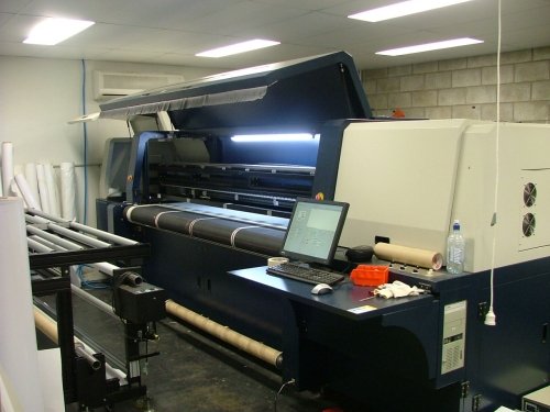
It can print on media 2.5 meters wide, and uses UV cured ink. Its mostly used for printing "for sale" corflute signs for the local realestate businesses. The head, showing the separate ink heads and a UV lamp at each end. 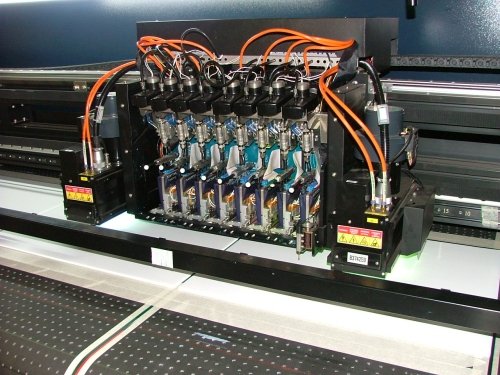
And here are a few corflutes being printed for a local Christmas fair. 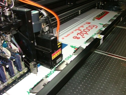
The printer will print onto any surface, and the ink dries as soon as the UV lamp has passed over. I'm tempted to see how it goes at printing circuit boards. Glenn The best time to plant a tree was twenty years ago, the second best time is right now. JAQ |
||||
| GWatPE Senior Member Joined: 01/09/2006 Location: AustraliaPosts: 2127 |
Hi Gizmo, The resolution and pinholes will be the key. Printing directly onto copper sheet? The etching should be easy to test with the artwork you have pictured. As long as the ink is acid proof. Gordon. become more energy aware |
||||
| Dingdoc Regular Member Joined: 23/09/2009 Location: AustraliaPosts: 76 |
Pete Re the price of UV cure catalyst - approx A$25 to do 4l & $50 to do 20l. It comes as a powder which is mixed thoroughly with the resin - I think most polyester resins work with it but I use a 'Surfboard' grade which is water white rather than the 'boat' grade which is often coloured. They recommend not dividing the powder before mixing with resin but I get mine in 1l lots and have had no problems - I do mix the powder very thoroughly before accurately dividing it. I can give you the name of the supplier in Vic if you want to get some to try or you could get some pre-mixed if you have a local board maker who uses it - not too many in Oz any more - most boards being made cheaply overseas. Also, have done some vac bagging but mainly on epoxy boards - use a 'fridge compressor for a pump & nylon peel ply. (Sorry about being off thread with this - will move any further comments to the new one) PS have ordered some UV Led modules to try with it. Glen Thanks for the photos - a most impressive printer. It makes my A1 size plotter look like a midget!! What ink does it use? - if its available it might be worth experimenting with in the Epson provided its viscosity is low enough and it turns out to be etch proof - hope you give it a try. Also, is it water based or organic solvent? (Sorry, lots of questions) Trev |
||||
| Dinges Senior Member Joined: 04/01/2008 Location: AlbaniaPosts: 510 |
Nice toy, Glenn! You could make *very* large PCBs with that one.... 
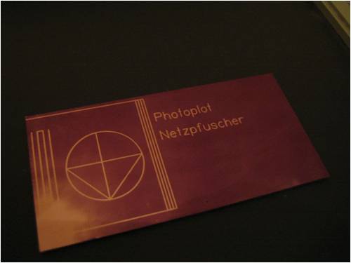
Whilst reading another forum (with some cool toys - it added a few new projects on the to-do list, such as a building an induction bearing heater: http://4hv.org/e107_plugins/forum/forum_viewtopic.php?74994; also came upon some very familiar names in that forum, LOL) I stumbled upon this: http://4hv.org/e107_plugins/forum/forum_viewtopic.php?66471 They're using a flatbed plotter with laserdiode for directly plotting the PCB traces in the photosensitive layer: 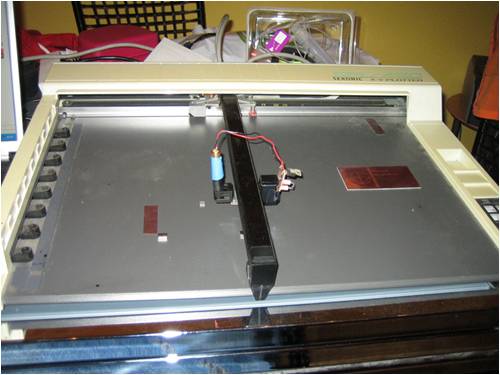
Interesting idea that is, hadn't thought of that yet. And you probably don't need a BlueRay laser, an UV LED with proper optics to focus it into a small spot may work too. Have recently built a laserdiode driver for an IR laser diode (out of an old 24x CD burner), should work for driving a BlueRay laser too: 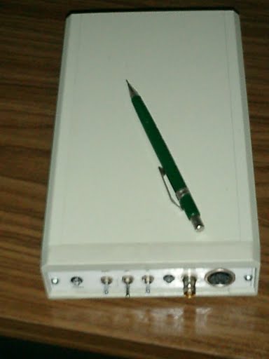
Pity my only plotter (HP7550) isn't a flatbed one. Using a BlueRay laser shouldn't work only with a flatbed plotter but also with a CNC mill. Interesting innovative solutions. Peter. |
||||
| Downwind Guru Joined: 09/09/2009 Location: AustraliaPosts: 2333 |
There is some neat toys there (in the links Peter posted) and a good read on some of the projects others have created. For anyone thinking of making a cnc machine it is not so easy to get perfect accuracy and would think it to be much better to build a cnc router to drill the holes and use a paper printed copy to produce the artwork. It is much easier to hit the print icon and produce the artwork than to have a computer dedicated to a plotter to expose the image directly onto a board. The exposure part of making a board is easy, it�s the little bloody holes that drove me insane. Most of the newer cnc engravers are now laser and will do pcb�s easy and was told they will even burn the holes to. Would be great if you have a spare $10K plus. A dollar or K outside my budget?? Peter, I did enjoy the read and a good link to some great ideas. Thanks for posting them. What was involved in the laser driver you built? Trev, (Dingdoc) I was looking for something earlier and found a board I had made with 2 rows of uv leds on it (40 in total about 6� long) it was configured for 20 volts,(mistake) sitting here doing nothing if it is any good to you, and you want something to test the uv resin with. Think you said you have ordered some, but this is here if you want it. Send me an email and I will stick it in the post to you. (doubt if I will use it) I think you are only at Victor. By memory the leds on the board I made was slightly brighter than the clusters but not easy to tell. ( to long ago. KRAFT disease {Kan�t remember a fuching thing} ) Glenn. Nice work tool you get to play with. When are you going to stop amazing me with the many talents you have and the vast range of things you do and have done. Many people have 1 or 2 jobs in life, as for yourself I stopped counting. It would be an interesting project to place a data logger on your brain. Hold on! A few quick calculations show it would only blow the power fuses unless we had a flux capacitor??? Lol. How much ink can the printer lay down before it starts to smudge, or do the uv solve this problem. Pete. Sometimes it just works |
||||
| Dingdoc Regular Member Joined: 23/09/2009 Location: AustraliaPosts: 76 |
Thanks for the offer of the LEDs Pete but I have ordered some modules from overseas and am waiting for them to arrive, so I will try them and let you know if they work. Sorry about the late reply - I tried to email you a couple of times but I don't think you received them. Trev |
||||
| Dingdoc Regular Member Joined: 23/09/2009 Location: AustraliaPosts: 76 |
The UV LED modules arrived and I removed the Aluminium backing from each and assembled and wired them up on a piece of Masonite for a quick test. 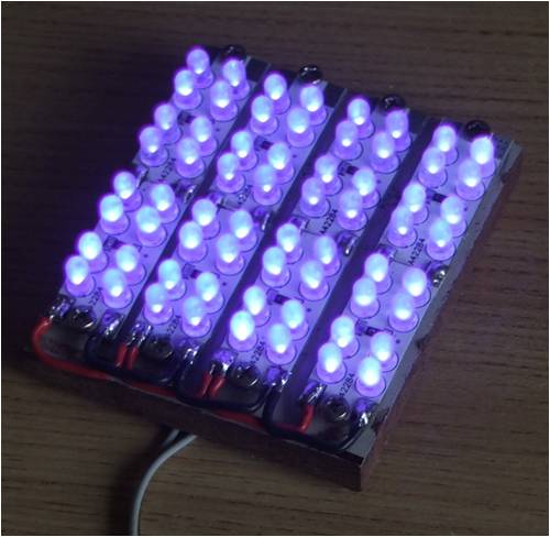
At a distance of about 150mm they will cause a sample UV set polyester resin to gel in about 5 sec. After 30sec it has reached the hard gel stage, so I am very pleased with the results. Now all I have to do is organize a 12v power supply capable of a couple of amps for use in the shed. Thanks for alerting me to them Pete. Trev |
||||
| Downwind Guru Joined: 09/09/2009 Location: AustraliaPosts: 2333 |
Thats not a bad result in setting times, you would have to be pleased with that. For around $10.00 its a good cheap option and much easier than building the boards yourself. Pete. Sometimes it just works |
||||
marcwolf Senior Member Joined: 08/06/2009 Location: AustraliaPosts: 119 |
Hi Folks I make a few small PCB board for myself and have had a lot of success with the Kinsten brand. I use DipTrace to lay out the board and it has an excellent auto-trace function, plus the ability to change the pad size. I often make ultra-compact boards with 0.25mm tracks which run between IC legs. To print - I have a Dell 1320c Laser Printers and I use overhead transparencies. The blacks are very opaque with no gaps or points. My light box is a small UV Fluro 'Black Light' that I got from a hardware store. Its exposure time is about 90 seconds. As the box the fluro uses gets quiet warm I can also use it afterwards to increase the reaction speed of FeCL (Ferous Chloride) For Drilling I had the luck of getting a little LessStress drill platform which have about 5 Axes of movement (Long term plan is to make a little CNC unit from it) and the drill are reground bits from CNC machines (10 for $20 Ebay) After I give a quick spray of PCB Laquer to protect the board until use. Overall I am very happy with the results Hope this helps somefolks Dave Coding Coding Coding.. Keep those keyboards coding.. RAW CODE!!!!! |
||||
| Downwind Guru Joined: 09/09/2009 Location: AustraliaPosts: 2333 |
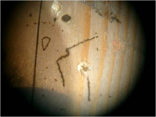
I tried an idea to print some text and outlines of the silkscreen layer onto the top of the pcb. Not a perfect result but ok for a quick attempt. I first reversed the image on screen. Printed it onto the waxy backing sheet you get stickers and lables on with a Laser Printer I soldered some header pins into the mounting holes. Aligned the header pins to the dots on the artwork and pressed down on top of a sheet of foam so the pins punched through the paper. Flipped it over and with a clothes iron on the hot setting applied a gentle pressure over the back of the paper moving it gently around the board. Wait for it to cool down and the paper peals away leaving the print behind. 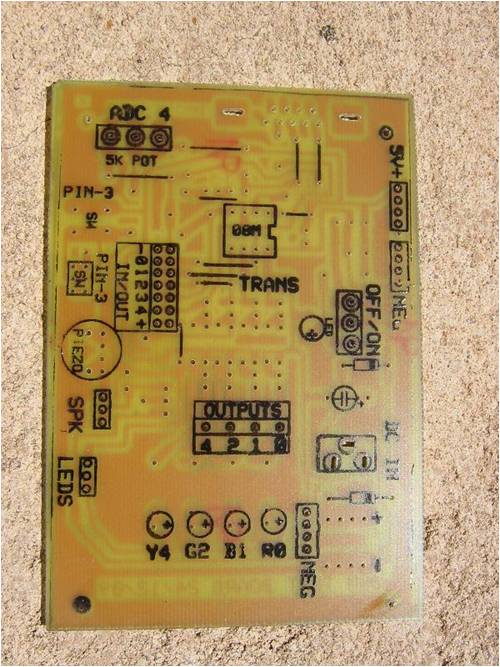
The same can be done for the copper side to print the tracks etc onto the copper for etching. It can be a bit tricky to get a good result, but if it dont work the first time than wipe the ink off with some acetone and start again. Pete. Sometimes it just works |
||||
oztules Guru Joined: 26/07/2007 Location: AustraliaPosts: 1686 |
Thats way cool.... will have to give it a go next time. .........oztules Village idiot...or... just another hack out of his depth |
||||
frackers Newbie Joined: 06/11/2009 Location: New ZealandPosts: 23 |
The laser printer idea is what I use for the PCB in the first place. Print with a laser onto matt inkjet paper (it has a china clay layer on it) observing the usual image reversal rules, iron it onto the plain copper board (no need for sensatised board!!) and soak the paper off in cold soapy water. Etch as normal, remove the thermoplastic laser ink with car (cellulose) paint thinners If you don't have a laser printer, the photocopier at the local library works well Robin down under - or are you up over |
||||
