
|
|
Forum Index : Windmills : Windmill DIY Analog MPPT Circuit
| Author | Message | ||||
Downwind Guru Joined: 09/09/2009 Location: AustraliaPosts: 2333 |
I did wonder on the choice of opamps myself, but think Bob mensioned he worked with what he had on hand. My favorite in opamps is the LM358, Data sheet low power, single supply voltage 3.5-32 volt dc, internally frequency compensated, dual in dip 8. Personally i think the 741 is garbage and would not design a circuit with one in it. But each to their own likings, and its a matter of what you are use to working with or what you have handy. LM324 data sheet With the use of single supply opamps and 1x v-reg you could power this from your batteries. Bob is there a couple of v-regs not shown in the schematic? Dave Have a go at putting a board design together, i would be interested in seeing your design. Pete. Sometimes it just works |
||||
| Gizmo Admin Group Joined: 05/06/2004 Location: AustraliaPosts: 5116 |
Hi Bob I agree with the other forum members that this post deserves a page of its own. The presentaion is very good and I can use your circuits, graphs, etc as they are now. Would it be OK if I put these posts together on one page as part of the main web site? Glenn The best time to plant a tree was twenty years ago, the second best time is right now. JAQ |
||||
bobshau Newbie Joined: 22/11/2009 Location: United StatesPosts: 27 |
Sorry it took me so long to get back to answering your questions; Out of town; just got back. Deer hunting in Northern PA. No, I didn't get one. Dave: With regard to converting the circuit into code. I haven't tried it but see no reason why it couldn't be done. Don B: Thanks for your kind remarks. With regard to the capacitors paralled with the 100uf: I used ceramic. Also, thanks for the tips for coupling to the MOSFET gates. I'll look into the 4050 hex non inverting buffer, as well as using a 50 ohm series resistance. Thanks again. Dave: With regard to the uA741's; Pete is correct; I used what was on hand. The LM324 would probably make a simpler circuit. Glad to hear that you are planning to build the circuit; I think you will be pleased with the performance. Let me know how it works for you. Pete: Thanks for the tip on the LM358. I really would like to use the batteries rather than the separate auxiliary power supply. Yes, I did use two voltage regulators. Glenn: Thanks for your positive comments. Please feel free to use the post as you see fit. I believe in the fundamental method for MPPT control described above; However, I am learning from the forum members that there are probably better choices of components than shown in my circuit diagrams. In the future, I would like to post an improved circuit diagram that implements forum recommended comments after I've checked them out. BobS |
||||
| GWatPE Senior Member Joined: 01/09/2006 Location: AustraliaPosts: 2127 |
Hi Bob, You have gone to a bit of trouble to make a cct that performs a function that a typical PWM chip, like a 494, or 3524 as well as a host of others, could do. I have been this road as well, and have a similar function maximizing cct using an LM3524 pwm chip on my 2m AxFx windmill. My windmill is probably an order of magnitude lower power than yours, so the heating in the mosfets in your design would probably amount to the power passed by the boost maximizer on my mill. OH for council permission to allow me to have a real windmill. 20foot rotor is up there. I would add additional components to give compensation for varying output load voltage, and some form of current limiting control. You have presented a workable cct, that others should have success with as well. Gordon. PS edit: A picaxe will perform this task quite badly, due to the low resolution ADC and PWM and the low cycle update rate. A 10kHz PWM output is not related to the update rate, or step resolution. become more energy aware |
||||
| bobshau Newbie Joined: 22/11/2009 Location: United StatesPosts: 27 |
Gordon: You are right; there are many PWM chips available that can be configured to serve the purpose of the (lowly) 555 that I used as shown in Figure 2. Requirement 4. at the beginning of this post reads: "Use analog components that are readily available at Radio Shack or on eBay." Putting that requirement aside, I'm learning that there are many ways to skin a cat. The key to the success of this approach is in the theory implemented in Figure 3. This theory is wrapped up in the equation: PWM control voltage (OP4, pin 6, Figure 3) = Constant V (R12) - (K x Vr) where Vr is proportional to gen speed (R20)) Implementation of this equation and the circuit's proper calibration (selection of constants) will result in providing MPPT from low wind velocities up to the velocity where Vr= Vbattery. The beauty in this approach is that calibration can be achieved using a simple procedure that inherently accounts for each user's individual wind turbine parameters. If you study Figure 3, you will see that it includes some logic to limit current at very low wind speeds. At high wind speeds the current is inherently limited by the control voltage equation described above. I suppose there are many ways to implement the above equation and the current limiting features. I would like to hear your's and other's recommendations and findings. Thanks for your comments. Blessings and peace. Bob S BobS |
||||
| GWatPE Senior Member Joined: 01/09/2006 Location: AustraliaPosts: 2127 |
Hi Bob, As you are aware, I have gone back to basics, and achieve the close to optimum windmill loading with a few passive components. You have a 20foot machine, yet your data only shows power levels up to 2kW. I would expect this size bladeset machine would be good to above 10kW. It seems like your alternator is designed for a smaller blade set[higher rpm] and with the bigger blades, you lost low end output. The switchmode boost allows use of this alternator in lower winds. This mill would now be considered a late cutin unit with the larger blades. A perfect candidate for voltage boosting. Matching the alternator to the load is what it is all about and boost ccts can do that. Cap multipliers or PWM DC-DC converters, achieve similar results. I suspect that other readers are hoping for a buck type maximizer as well. This is still possible, but there are other electronic issues at high power levels, as there isn't the parallel bridge rectifier system to handle the bulk power. Gordon. become more energy aware |
||||
Don B Senior Member Joined: 27/09/2008 Location: AustraliaPosts: 190 |
Hi again Bob, As indicated in my earlier post, I have been tinkering with MPPTs for some time, and this is the sum total of my experience to date. Theory tells us that the maximum possible output from the blades of a wind turbine occur at a particular tip speed ratio (TSR), which is the ratio of the tip speed to the wind speed. Thus, if the wind speed doubles, the blade RPM also needs to double. Unloaded alternators with permanent magnet excitation will output a voltage that is proportional to their rotational speed. If you double the RPM, you will double the output voltage. As you indicate, the output voltage of a loaded alternator is reduced by the voltage drop through the winding resistance (a function of current), and by the drop through the winding reactance (a function of current and frequency or shaft RPM). Theory also tells us that the available power in the wind tracks the cube of the wind speed. If you double the wind speed, your output power potentially increases by eight times. If you double the wind speed, then your alternator wants to put out double the voltage, less the amount of the increased internal voltage drop. In order for the alternator to output 8 times its previous power at this new voltage level, the alternator current needs to increase by four times. If the alternator load was a pure resistance then, by doubling the output voltage, the current also would double, and the power delivered would only be four times the previous value. The load resistance would actually need to be halved in order for the current to be four times its previous value. If the load is a battery with a more or less fixed voltage, then matching a wind turbine to it to permit maximum power to flow for any given wind speed within its range is quite an exercise. So long as the alternator output voltage does not exceed the battery voltage (ie spinning but below normal cut in speed), then useful power can be gained from a boost circuit such as yours. Once the alternator voltage equals, or wants to exceed the battery voltage, then you need a buck circuit to achieve maximum power extraction, however, buck circuits have their difficulties at high power, as Gordon points out. Another point that Gordon has made is that, by the time you need a buck circuit, there is so much wind power available that you usually don�t need to worry about any possible additional gains. The problem with a circuit that tries to track the maximum power point with only the turbine speed as its reference is that you don�t know the actual wind speed at any instant. In the absence of that information, you can�t know whether your turbine is spinning at the optimum speed for that wind. Unfortunately, real wind is constantly varying in velocity, so it is difficult to tune the device to give the best output for all winds within range. The only way that you can know that you are actually tracking the maximum power point, rather than some lesser degree of improvement, is to plot the output power (battery current would be near enough) against turbine speed (volts would be near enough). If the MPP is being tracked, then the current should have a squared relationship to the turbine speed (ie double the volts gives four times the current) Unfortunately, measuring the speed of the wind actually arriving at the turbine has its difficulties, as the instrument ideally needs to be directly ahead of the turbine. Other locations will degrade accuracy, but would still provide a big improvement in control. At one time I did have an analogue TSR tracking circuit operational, and one interesting finding was that I had to delay setpoint changes as the wind speed changed in order to let the turbine accelerate or decelerate to its new speed value. More recently, I have been experimenting with a boost and buck circuit controlled by a microprocessor and operating open loop. The idea is that the processor is constantly changing the voltage reference value for the alternator. The processor changes the value by a small amount, then pauses to see if there is an increase in output current. If there is an increase, then it adds a further small change in the same direction. If there is a decrease, then the next change is in the opposite direction. It�s a great theory, but I can�t say that it is outstandingly successful as yet. I am also probably complicating its task by having both a solar panel and a wind generator connected to it at the same time. I think that Gordon�s scheme of using capacitors in a doubler arrangement (see visual effect of capacitors thread on this forum) is probably the simplest and potentially most effective arrangement for wind turbines once the correct values have been determined. As your arrangement charges 48V batteries, this a great help. It is also sobering to think that Gordon has experimented largely with MPPT devices before arriving at the capacitor arrangement. It�s the KISS principle in operation, I guess. I also think that if anyone wants to pursue maximum power point tracking, they would be best off starting with a wind speed input together with their turbine speed, and perhaps some simple analogue circuitry controlling their boost circuit. Regards Don B |
||||
oztules Guru Joined: 26/07/2007 Location: AustraliaPosts: 1686 |
Firstly Bob, congratulations on a fine machine all up. Looking at your power graph, you have built a very low resistance machine. Looking at it from backwards off the graph, I get a cut in around 120-130 rpm at about 12-13mph.... thats with it's loaded/design TSR of about 7... I'm guessing. So cut in is in real life may be around 75-80rpm at unloaded TSR. On a 20 footer, that should leave you with enough room for a few in hand of fencing wire of low turns.... less than 30? This puts this machine squarely in the camp of a well designed late cut in- low resistance axial flux 20 footer... good for bursts of 6kw or more in the sub 30 mph winds I suspect. This has to be an absolutely perfect candidate for the style of converter you have designed. It's not how I was going to do it, but you have crafted a working, easy to replicate, common parts converter, which seems to have replaced the part of the capture curve you have designed out of the stator, and pulled it back in. You must have decent blades to match that graph. A cp. > .3 I suspect.... Glass or wood? My congratulations. Many talk about it, not many do it. I've talked about it, and I designed my 4m mill accordingly for late cutin specifically to take advantage of the power curves matching up better in this configuration, and was going to build a converter. (design cut in of 11-12mph at loaded TSR, actual unloaded tsr cut in about 6mph). I never built the converter, as I discovered that we don't have winds less than about 8-9mph. It is either 9 or more, or dead still (rare)..... so a converter was never required.... part of living in the roaring 40's part of the world I guess. So on what we call calm days, it ticks along at 80-500 watts. Because of the low turns/resistance, on the windy ones 500w-3kw or so. I still mean to do it one day as an exercise. If you are going to take on board some of the comments, so far, I would agree that a PWM chip with on board Fet driver simplifies things, and I would sense the current rather than the implied voltage as Flux suggests for this style of control But it is working well as it is.... so perhaps just sort out the switching of the Fets at least. I still like to see analogue stuff. For those that don't fully understand what this really is.. It is essentially a voltage controlled boost converter. Ideal for Bob's mill (and mine). If you have an early cut in mill, this is not what you want. It will be a waste of time.... you really need a buck to avoid stall. If you have a late cut in mill and poor winds, this will be a godsend. If you have an intermediate cutin mill, it will be of lessor value, and probably marginal for small ones in this range. The later your cut in, the more useful this will be. Once again Bob, well presented, and looks to be a great working project. ................oztules EDIT: Not sure I would call it mppt in the strict sense, as it will not suite most axial mills.... I say most, as most of us are greedy and wire them for early cut in... where this would be of very limited help.......perhaps call it a boost converter for late cut in mills. Probably quite useful for the motor conversion crowd too, as with their small diameter magnet rotors I seem to recall that they cut in late. Edit2: [quote]Gordon: You are right; there are many PWM chips available that can be configured to serve the purpose of the (lowly) 555 that I used as shown in Figure 2 [/quote] Actually, most pwn chips have a regulated vref for your use (usually about 5v), a fet drive, and a few op-amps on board... and a dead time control accessible as well, a single chip may replace most of the discrete components. Switching at 30khz with some ferrite may bring the inductor down in R as well... just a thought. Village idiot...or... just another hack out of his depth |
||||
| bobshau Newbie Joined: 22/11/2009 Location: United StatesPosts: 27 |
Hi Gordon, you wrote: "As you are aware, I have gone back to basics, and achieve the close to optimum windmill loading with a few passive components." Yes, congratulations on your excellent work. I plan to model your method on my windmill using TINA II. I'll let you know how it goes. You wrote: "You have a 20foot machine, yet your data only shows power levels up to 2kW. I would expect this size bladeset machine would be good to above 10kW." I only showed data in the range of the MPPT booster circuit. The windmill system is limited to 3600 watts by the OutBack GVFX3648 inverter. I begin furling at around 18mph and see transient inverter output of over 4kw during furling. At 3600 watts output, the generator is producing about 6100 watts and stator temperatures are heading toward 300F (150C). The winding 200C insulation won't stand generator steady state loads up to 10KW. I agree with your observation that my alternator is designed for higher rpm. Actually, after incurring several stator burnouts, I worked hard to provide a low resistance high temperature stator that is resistant to burnout. I vacuum cast each coil separately using high temperature resin. If you are interested, please see: http://www.fieldlines.com/story/2009/3/2/171331/4786 The MPPT booster works well with this design. A buck converter would be usefull to those that don't have a system with high cut-in. After Vr reaches Vbattery, my windmill begins furling and doesn't need it. Thanks for your comments. Blessings and peace. Bob BobS |
||||
| bobshau Newbie Joined: 22/11/2009 Location: United StatesPosts: 27 |
Hi Don, Thank you for the review of what is happening with the windmill electricals. You obviously have an excellent understanding. I'm impressed. I am in complete agreement with what you said with the exception of the following statement: "The only way that you can know that you are actually tracking the maximum power point, rather than some lesser degree of improvement, is to plot the output power (battery current would be near enough) against turbine speed (volts would be near enough). If the MPP is being tracked, then the current should have a squared relationship to the turbine speed (ie double the volts gives four times the current)" Two questions come to mind: (1) Wouldn't we see the same effect (double the volts gives four times the current) if the TSR was held constant by the tracking system but not at the peak? (2) Wouldn't the following test tell us that we were near the maximum power point? Observe if generator speed (DC �+� voltage Vr) doubles when the MPPT is disabled during a nearly constant wind condition. This test should be done in steady wind conditions at velocities under main cut in, but exceeding the cut in voltage set point with MPPT. Repeat many times to gain confidence with the readings; wind rarely remains constant during the 15 seconds required to do this test. The above test is easily done with PWM control; it requires a multi pole switch with the cap approach. Don, thank you for your insights. Blessings and peace, Bob BobS |
||||
| bobshau Newbie Joined: 22/11/2009 Location: United StatesPosts: 27 |
oztules, Thank you for your insights and kind remarks. You had a few questions, as follows: "Looking at your power graph, you have built a very low resistance machine. Looking at it from backwards off the graph, I get a cut in around 120-130 rpm at about 12-13mph.... thats with it's loaded/design TSR of about 7... I'm guessing. So cut in is in real life may be around 75-80rpm at unloaded TSR. On a 20 footer, that should leave you with enough room for a few in hand of fencing wire of low turns.... less than 30?" Yes, I use 12 coils, each wound with three strands of #14 awg, 26 turns. The total resistance at room temperature including wiring to the battery is = 0.156 ohms per phase. Please see this post for more info on coil, blade, rotor, tail, tower, designs: http://www.fieldlines.com/story/2009/3/2/171331/4786 You wrote: "It's not how I was going to do it, but you have crafted a working, easy to replicate, common parts converter, which seems to have replaced the part of the capture curve you have designed out of the stator, and pulled it back in. You must have decent blades to match that graph. A cp. > .3 I suspect.... Glass or wood?" The blades are twisted and tapered made in accordance to a computer program that I downloaded from the Fieldlines site. They are made from a laminated plywood core, cast in fiberglass foam resin, and wrapped with as many as 12 layers of 9 mil fiberglass cloth. Sanded and painted. See the above fieldlines link. Also, thank you for your helpful suggestions on the design of an PWM controller and how to reduce the resistance of the induction coil. Your comments are much appreciated. Blessings and peace. Bob BobS |
||||
| oztules Guru Joined: 26/07/2007 Location: AustraliaPosts: 1686 |
I was able to look at your fieldlines story....anything fieldlines at the moment is a chore to be sure... Very impressive and interesting approach to building a biggie. A lot of thought has gone into it. I like the heat exchanger idea.... neat. You clearly see the merits in boost converting and designed for it by the looks. It is the best way to go I think..... I just don't need it. It's just another "bursts of 3kw" day here. Here is the circuit ( from Flux) I was to base mine on. I would have used a different pwm chip, so I would not need the driver. I have a few hundred l4990 here, which incorporate a driver. However, tl494's are in abundance on any PSU computer power supply, and a few 3 cent driver trannies in a totem pole solves the driving problem. 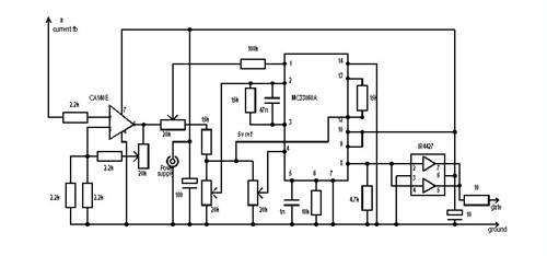
You have it under control as I see it anyway. Best wishes with it. ...........oztules Village idiot...or... just another hack out of his depth |
||||
| Don B Senior Member Joined: 27/09/2008 Location: AustraliaPosts: 190 |
Hi again Bob, In your post of 5-12-09 on this thread you ask if you would not also see the same power tracking (double volts, 4 X current) with your device if you were tracking somewhere off the actual maximum power point. The attached family of power and torque curves for a range of wind speeds leads me to think that the answer is no, as it appears that the extractable power will only follow a cube law at the optimum TSR. Still pondering that one though, particularly the effect that you would see if operating on the back of the power curve (ie above optimum TSR). Your second question asks whether you could confirm that you are operating at the maximum power point by removing the load under steady wind conditions and noting whether the alternator output voltage doubles. Having looked a few TSR/power curves, I am inclined to think that this is probably a fair test, as most are similar in shape to your �Quixote� curve. You could be more confident of this if the Princeton plot was for your specific blade design, but I have no doubt that you are well in the ball park. The following comments might be of interest concerning your electronics. They represent things that I have found out the hard way. Your air cored inductor will have a reasonably extensive flux field around it. Be careful of adjacent metal, such as the aluminium heat sink for the FETs, as this can act as a shorted turn if too close and parallel. Best to fix the coil at right angles to the aluminium, and keep any other metal away. I am not sure what actual DC voltages that you have to drive your electronics, but being derived from 18VAC transformer windings, I imagine that you could have something around plus and minus 24VDC. While this voltage might whip the 741 op amps into some sort of performance, I am concerned as to what voltage the LF351 is applying to the gates of your IRFP150 FETs. Maybe also I am missing something, as you talk about having +/- 12V control voltage, so maybe you have the transformer primaries connected in series?? From the LF351 data sheet, it looks as though the output voltage will be around 1.5V less than the supply voltage, so maybe it will swing between +/- 10.5V, or maybe double that? A voltage of +10.5V would be fine for the FET gate, but I don�t know what happens when the 351 switches low. Does it apply -10.5V to the gate? Generally with FETs you should apply no more gate volts than needed to fully drive them on, and no less than zero to drive them off. Commonly, you would fit a Zener of just above the rated gate voltage (maybe a 12V Zener in this case) between the gate and the source both to swallow any positive spikes, and to limit any negative voltages on the gate to less than -1V. These Zeners should be fitted right at the gate terminal to swallow any spikes induced in the gate wiring. Note also that if you fit Zeners at the gates you will need a series resistance in the gate lead, particularly if you leave the 351 powered as is. Maybe you could consider powering your 351 from +12V and ground, rather than +/-12V. FETs should be set up to switch on or off as quickly as possible. This means that the gate voltage should go from positive to ground or vice versa as quickly as possible, and should have the capacity to charge and discharge the gate capacitance as quickly as possible. Unfortunately, op amps used as comparators don�t necessarily switch cleanly, as they can tend to dither when their inputs are at equal voltage. While it is possible to use a small measure of positive feedback around the op amp to hasten its switching, (or per haps use an actual comparator) it is still preferable to use something like the hex driver to switch the gate cleanly, and with sufficient grunt to quickly charge and discharge the gate capacitance. On the topic of fast switching, the effect of fast changes in current (and/or voltage) on leads associated with the FETs is exactly the same effect as having them operating at very high frequencies. They need to be kept as short as possible, and clear of each other. Curly tails in the wiring are inductances, and these serve to slow and radiate the switching impulses, and should be eliminated (in the Beta version). Your IRFP150 FETs have an on resistance of around 0.055 ohms each, and I believe that you have three in parallel, giving a potential on resistance of .0018 Ohms. If they are passing, say, an average of 10A of current in total, their individual power dissipation will only be around 0.6W each, which I would not expect to make them even perceptibly warm. Of course, the power dissipation increases with the square of the current, but I would still think that noticeable warmth in operation suggests the need to look more closely at the cleanness of the switching. An oscilloscope is an inestimable help for this. Finally Bob, I was most impressed at the description of your complete turbine set-up that you gave to Oztules. You have obviously gone very thoroughly and methodically into all aspects of your project, and the results do you great credit. As Oztules indicated, arranging the alternator output voltage to be such that a boost circuit can be usefully employed for the lower (and otherwise wasted) winds prior to what would be the normal cut in point certainly lets you suck in the last few drops of the free stuff. Regards 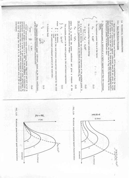
Don B |
||||
| bobshau Newbie Joined: 22/11/2009 Location: United StatesPosts: 27 |
oztules, Thank you for posting the PWM circuit that Flux provided to you. I'll check it out. Also, thanks for the encouragement. Blessings and peace. Bob Don B, Thanks for taking the time to answer my questions and providing the constructive comments and recommendations for the PWM Boost circuit. I believe their implementation will improve circuit efficiency. Lots to chew on. Blessings and peace. Bob BobS |
||||
| GWatPE Senior Member Joined: 01/09/2006 Location: AustraliaPosts: 2127 |
Hi Bob, once you drive the mosfets harder and square up the switching edges, you open up a new can of worms. RFI interference. You will need to pay a lot more attention to loose conecting leads and probably need to go for a PCB layout. The curly wires are not part of the required layout. My early designs like you have wiped out TV and radio reception for me and the neighbours. The cap boost arrangements do not suffer this problem and open style wiring is still possible. It is difficult to screen the high power switching energy emanating from air cored inductors. Gordon. become more energy aware |
||||
| bobshau Newbie Joined: 22/11/2009 Location: United StatesPosts: 27 |
Hi Gordon, Thanks for the "Heads up" regarding possible RFI interference after squaring up the switching edges. Right now, the circuit works great as it is. I don't believe I get any more RFI from the MPPT booster than I get from the Outback inverter based on the amplitude of "static" in my AM radio earphones. We get no interference in the house. All this without any attempt to shielding. The heat sinks are able to maintain MOSFET temperatures well below being "hot to touch". They are able to carry over 20 amps to the 52 volts of battery bank (1000 watts). Maybe, I should not fix what is not broken. By the way, I'm almost done comparing the Cap booster to the PMW booster for my 20'. I think I'll publish the results today or tomorrow. Blessings and peace. Bob BobS |
||||
| oztules Guru Joined: 26/07/2007 Location: AustraliaPosts: 1686 |
[quote]The heat sinks are able to maintain MOSFET temperatures well below being "hot to touch". They are able to carry over 20 amps to the 52 volts of battery bank (1000 watts). Maybe, I should not fix what is not broken.[/quote] If temp is stable, and no rfi, then leave well enough alone is a fair deal I think. Because it is a booster, it won't see any unforseen power surges as it would if it were a buck carrying full power. So even though it may not follow the ideals of PWM practice, it works. It has tested all limits it is able to incur....and is still alive and well, and so will continue to work indefinately. It seems to avert the RFI by slope switching.....small expense in efficiency. With a 20 footer..... you'll never be aware of this loss 
I'm a great believer in don't fix what aint busted.... but I'm a lazy slob too 
...........oztules Village idiot...or... just another hack out of his depth |
||||
| bobshau Newbie Joined: 22/11/2009 Location: United StatesPosts: 27 |
Thanks oztules. I plan to incorporate some of Don B's and your recommendations on the next one I build. Shorter leads, better driver, different op amps, etc. Much appreciate your comments. Blessings and peace. Bob BobS |
||||
| GWatPE Senior Member Joined: 01/09/2006 Location: AustraliaPosts: 2127 |
Hi Bob, I agree with oztules re the mosfets in your application. This is a large windmill and the slow switching of the mosfets will keep the RFI in check, with some associated losses. The boost maximizer I made that is on my older AxFx mill passes all the mill power. I have a single mosfet with no heatsink [SMD mounted on PCB] and the power passed is up to 450W[close to 20A at around 22V]. There are pics and description of operation on the early MPPT thread. Before I looked at micro alternatives. Mine is into 3rd year of operation now, since 2006. PWM is the best solution for multi kW windmills. Maybe the commercial operators will adopt the system you have presented on the big windmills. Gordon. become more energy aware |
||||
| bobshau Newbie Joined: 22/11/2009 Location: United StatesPosts: 27 |
Hi Gordon, Glad to hear that your MOSFET driven boost maximizer has worked reliably since 2006. If you add a few more op amps, etc, you could teach it to do MPPT. Since our windmills require our time and $, we might as well get the most out of them. You said: "PWM is the best solution for multi kW windmills." I agree. They allow easy calibration to assure they run at the maximum power point for a wide range of windspeeds. For this very reason, PWM is a good choice for the smaller mills, as well. Blessings and peace. Bob BobS |
||||
| The Back Shed's forum code is written, and hosted, in Australia. | © JAQ Software 2025 |
