
|
|
Forum Index : Electronics : Newbie requiring help!!
| Author | Message | ||||
Downwind Guru Joined: 09/09/2009 Location: AustraliaPosts: 2333 |
I worked in Siberia for 2 years and the average winter temp was -40C deg. So i can relate to your present freeze, although you still have a little to go to equal Siberia. It was +40C here last week and +26C here now. And NO! i dont want to swap you. Pete. Sometimes it just works |
||||
Smoothy Newbie Joined: 12/01/2010 Location: United KingdomPosts: 15 |
Quick question... best solder to use? and size of tip? I can put it on order aswell! Smoothy PS Long term plan is to complete the ship, son completes apprenticeship, then move to OZ!!! �The scientists of today think deeply instead of clearly. One must be sane to think clearly, but one can think deeply and be quite insane.� Nikola Tesla |
||||
| Downwind Guru Joined: 09/09/2009 Location: AustraliaPosts: 2333 |
As for solder i prefere 0.6-1mm dia. but its a matter of what you can get your paws on. Just go for a small dia. The larger the solder dia normally mean larger resin content and the stuff ends up everywhere. The tip depends on the iron you have, I use a weller iron with a base station, It is a good iron that heats fast with good tip temp control. It allows me to use the smallest tip i can buy (0.6mm point) Dont go above 2mm in tip size if you can help it and as components are getting smaller all the time the smaller the tip the better. Its no fun soldering with a crow bar and large solder. If you come to Oz make sure you leave that mongrle weather behind as i dont want it here.(+10C is cold enough for me now) Pete. Sometimes it just works |
||||
| Smoothy Newbie Joined: 12/01/2010 Location: United KingdomPosts: 15 |
Ok, so I just placed the order! I also added 2 x PICAXE-08M CHIP (RC) 2 x 9 WAY STRAIGHT PCB D SOCKET (RC) and 2 extra stripboards. My only concern is, my laptop doesnt have a 9 pin input, only usb or 15 pin vga. Can I make a 9 pin to 15 or usb to dump info into picaxe?! or, is there an easier way to transfer data using a different socket or a 15 to 9 converter? At the moment, temp is -3c here. had no mains water since week b4 xmas and internal tanks (4000 litres) have run dry. Time to take a pick axe ( no pun intended!) to the icy sea and go have a wash!! Smoothy EDIT: Just re-read your post Beginning picaxe for old dogs and noticed Tinker has a 9 pin to usb cable. If I bought the usb plug and male 9 pin connector I could make one of these leads up with a little guidance. Aternatively, as its only 3 cables, maybe a usb on pcb instead of 9 pin d socket �The scientists of today think deeply instead of clearly. One must be sane to think clearly, but one can think deeply and be quite insane.� Nikola Tesla |
||||
| Downwind Guru Joined: 09/09/2009 Location: AustraliaPosts: 2333 |
Hope you ordered a female 9pin D socket. A couple of 8 pin ic scockets would be an advantage to. Rule of thumb!! place every ic on a socket so when ordering components always buy a socket for each ic you buy. You will thank yourself for doing it sooner than later. You will need some resistors to so should have said about the picaxe b4 placing the order. O-well we will find a way. You will need to get a USB to serial cable to program the picaxe. As the picaxe is made in the UK and REV-ED the supplier lists a USB to serial cable for about 7 pound but you might find them cheaper at a computer supplyier. Rev-ed is the link in the picaxe stuff for downloading programming editor, if you follow that you should find the cables. Make sure its got the 9 pin D socket on it as then you can use it with other serial equipment. An expression here is "A pommy bath" basically means a wash under the arm pitts and not much more. Think i would settle for that compaired to a -3C dip in the ocean. Pete. Sometimes it just works |
||||
| Smoothy Newbie Joined: 12/01/2010 Location: United KingdomPosts: 15 |
Just phoned supplier and added a couple of 8 pin ic sockets. I have ordered loads of resistors so that shouldnt be a problem aswell as having 1 or 2 (ahem!) in stock! My supplier does stock usb to serial cable but its way more than �7!! I think ill buy the components and hunt the web for the wring as itd be cheaper! I have got an old serial cable I can butcher!! Id prefer an 'Aussie bath'..... A long soak in Fosters!!!! Smoothy �The scientists of today think deeply instead of clearly. One must be sane to think clearly, but one can think deeply and be quite insane.� Nikola Tesla |
||||
| Gizmo Admin Group Joined: 05/06/2004 Location: AustraliaPosts: 5036 |
You know I've had a few requests for a component list for that project 
At first I wondered why anyone would want a component list, just look at the circuit and grab the bits from the component drawers as you build it. But then I realised, not everyone has drawers full of components. So it makes sense to have components lists, like a shopping list ( I dont use those either, and always forget something ). I shall endeavor to improve my old ways. 
Glenn The best time to plant a tree was twenty years ago, the second best time is right now. JAQ |
||||
| Smoothy Newbie Joined: 12/01/2010 Location: United KingdomPosts: 15 |
Well, you have, certainly helped me as Id have forgotten things like sockets and connected straight to board! As you said, its a learning curve and you never stop learning. Im used to playing with LED's but making a controller for them is new so im looking to glean valuable experience from it. I'll let you know when components arrive. Im looking to assemble fairly fast as I really want to get off grid. Mains electric for the ship is soaring in price and anything I can do to reduce costs and become self-sufficient is a must. Perhaps, for the sake of newbies, such as myself, we could start a topic detailing the construction of the controller including pics. It may reduce the amount of repeated questions asked. What do you think? Smoothy �The scientists of today think deeply instead of clearly. One must be sane to think clearly, but one can think deeply and be quite insane.� Nikola Tesla |
||||
| Downwind Guru Joined: 09/09/2009 Location: AustraliaPosts: 2333 |
I think it would be good if you tracked your project and posted the development. It takes a lot of time and effort to put all the information together and post the design in the first place. It would have taken Gizmo less than an hour to build the whole circuit, but many hours the tell you how to build it. It is always good to see how others follow in your footsteps and any information you post will help someone else standing in your shoes. If you make it worthwile Gizmo might even add it to the project on the front page. 
Im sure Gizmo gets a kick out of knowing a circuit he threw together from a handful of components on a lazy afternoon and bothered to post, has inspired someone else in another part of the world to get off his ass and have a go at building his circuit and may lead to a bigger project in electronics. Pete. Sometimes it just works |
||||
| Gizmo Admin Group Joined: 05/06/2004 Location: AustraliaPosts: 5036 |
I've added a component list to the TL084 based controller page here. If you guys think the format looks OK I'll do the same for the other projects. Glenn The best time to plant a tree was twenty years ago, the second best time is right now. JAQ |
||||
| Downwind Guru Joined: 09/09/2009 Location: AustraliaPosts: 2333 |
I like it. The parts list looks neat, and will help with answering question about the circuit. Think there was 2 x 1N4004 diodes with one across the relay. Perhaps a IC socket as well. The LM78L08 is harder to find so a "Or LM7808" might help. Pete. Sometimes it just works |
||||
| Gizmo Admin Group Joined: 05/06/2004 Location: AustraliaPosts: 5036 |
Done. The best time to plant a tree was twenty years ago, the second best time is right now. JAQ |
||||
| Smoothy Newbie Joined: 12/01/2010 Location: United KingdomPosts: 15 |
Pete, Glenn, Top marks for making life easier for a circuit virgin such as myself. My parts are due on Monday so I shall wade in and begin assembly as soon as they arrive. I'll start a new topic and include pics in the hope that other virgins become as inspired by your ingenuity as I have been. I cant thank you both enough! Would it be ok if I reference this site on my website? I shall be replicating the pictures of my construction on my site but all credit shall be given to this site for Research, Design and development as well as all rights regarding replication. After trawling the net to find a controller, yours is the only site I found that offers detailed schematics and personal assistance without a demeaning attitude. For that, you should be commended. Simon �The scientists of today think deeply instead of clearly. One must be sane to think clearly, but one can think deeply and be quite insane.� Nikola Tesla |
||||
| Downwind Guru Joined: 09/09/2009 Location: AustraliaPosts: 2333 |
Hi Simon, I threw together a bare bones 08m picaxe circuit for on veroboard. Many other things can be added as you need. It will allow you to fire a picaxe up and control a few leds to start with. There is no voltage regulator in the circuit so you will need to find a DC power supply of 5Volts. 3 x AA batterys will be ok as this will give 4.5 volts and the picaxe will work down to 3 volts. 5 volt is the maximum input voltage. The output pins will only handle about 30mA and will only drive a led so any greater current load will need to be controlled with a transistor or likes of. This should give you a starting point to have a think about when your goodies arrive. 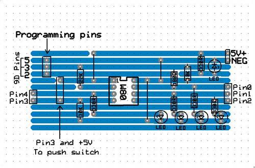
This PDF here should be a clearer image than the screen shot. .2010-01-17_221835_Veroboard_08M_circuit.pdf Pete Sometimes it just works |
||||
