
|
|
Forum Index : Electronics : Suggestions for Breakers
| Author | Message | ||||
Downwind Guru Joined: 09/09/2009 Location: AustraliaPosts: 2333 |
Karl, The stud diodes. At a further look i see the vendor has cathode stud (-) and anode (+) stud diodes. It be well worth getting a set of each. This will make building a rectifier real easy. What you do is screw 3 anode diodes into a aluminum block and attach your +DC cable to it. Then do the same with 3 cathode stud diodes and attach your -DC cable to it. Then take one of the leads on the diodes form each block and connect it to a phase wire, and the same for the other 2 phases and you have a 260 amp rectifier. Almost bullet proof! One diode the battery end should be enough and may work better than 2, as diodes are not always the same and with 2 in parallel one may do more work than the other. Besides if you are pushing 130 amp (6Kw) to the batteries than you have bigger problems to deal with than diodes. 
Pete. Sometimes it just works |
||||
KarlJ Guru Joined: 19/05/2008 Location: AustraliaPosts: 1178 |
OK ok my pics are crap, making a mends here. Pictorially hope its right as I laminated it! Diode at the PL Load- to Batt Pos is a catch diode BTW 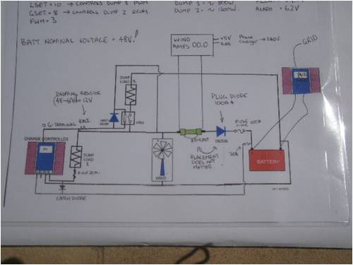
I had this kicking around the shed, works OK but dont know the rating, I'd imagine 40-50A 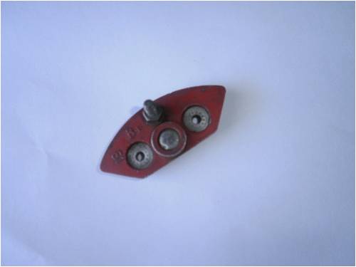
I was thinking I'd bolt it straight to the battery and the windmill to the post, bolt the terminal for the inverter on the other side and done! Luck favours the well prepared |
||||
| GWatPE Senior Member Joined: 01/09/2006 Location: AustraliaPosts: 2127 |
The voltage rating of the diode will be important. These car alternator types can be low voltage, and easily go short reversed. When the windmill power is low and the battery ius fully charged, the diversion load will drag the mill volts to close to 0V. The diode will be fully reverse biased, and Full battery volts will be across the diode. Gordon. become more energy aware |
||||
| Downwind Guru Joined: 09/09/2009 Location: AustraliaPosts: 2333 |
The only change to the wiring that you might consider is to take your dump loads off after the shunt and before the diode, Not that it will matter greatly but will allow you to see what current you are dumping as well. Must say your crayon drawings has improved greatly. It was only a cheap shot at your last drawing and a drawing is still much better than words only, regardless how basic it is. Sorry if i hurt your feelings. Think i would leave that diode in the shed and go for the stud ones and not have the worry. As you say the diode specs are unknown???? Pete. Sometimes it just works |
||||
| KarlJ Guru Joined: 19/05/2008 Location: AustraliaPosts: 1178 |
yeikes, so no good is the answer I get from that. You beauty, inverter arrived courtesy of Matt Lyons forum member and energymatters. 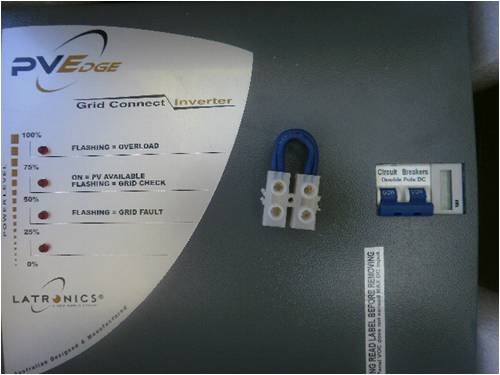
Also ontop is the fuse link to the batt that I knocked together, 3 lengths of 35A fusable link wire together. resistance is less than I can measure but cant see any losses there. So Gordon/Pete, cant see any issues with my schematic? not perfect but closer than most will ever get to a good circuit. As for the hurt feelings, MUCH tougher skin than that! no probs, keep it coming. and .....some of the best things in history were designed on the back of a serviette! Interestingly enough this topic is posted every other day on energymatters forum BUT... they dont have you guys...only me! Karl Luck favours the well prepared |
||||
oztules Guru Joined: 26/07/2007 Location: AustraliaPosts: 1686 |
Karl, this is why I wrote what I did. It is a recent post from DanB of otherpowerhere Says it all really..... you don't want the trick stuff on the mill side of the fuse. Battery side only... except the dump load itself.and that through rectifiers..... it's designed to cop it anyway. Gordon was right to put the voltage sense of the dump load on the mill side as well. ...........oztules Village idiot...or... just another hack out of his depth |
||||
| Downwind Guru Joined: 09/09/2009 Location: AustraliaPosts: 2333 |
Hi Oz, The schematics i put together on what i thought you were saying in text previuosly. I see your point with the DanB example. One question that comes to mind is if all monitoring is done from the battery side of the fuse, what happens if the fuse blows. As there is nothing to controlling the mill then, and you would have a runaway. Hence the thought of the earlier idea of a relay across the fuse. Seems like a damed if we do and a damed if we dont situation. I guess nothing is idiot proof as an idiot will always find a way to prevail. Pete. Sometimes it just works |
||||
| oztules Guru Joined: 26/07/2007 Location: AustraliaPosts: 1686 |
It's compromise after compromise...... Gordon rightly pointed out that the dump sense can be on the mill side of the fuse.... so if we lose fuse (mill will probably stop anyway.... unless you pull it yourself... hence fusable link... most unlikely) the dump will kick in on the higher voltage it would see immediately. Thats why I would prefer to see a ghurd style dump control. only a few dollars and would solve the problem... perhaps set it for a few volts higher than the real system then it maybe an add on for this system perhaps. That makes it just about bomb proof. Your relay scheme should do the same thing. I thought it was fine..... maybe a led and resistor across it for tell a tale too 
In my system, it won't allow the mill to run unless the batteries are connected. A big relay sits across the three phase of the mill. It is NC, so if no battery seen, then shut down. Another op amp senses over voltage, and does the same thing and latches off. The current draw is about 150 ma or more..... Gordon is horrified. Just another advantage of an axfx  I've seen it shut down in over 50 mph winds... takes about 2 seconds I've seen it shut down in over 50 mph winds... takes about 2 seconds
...........oztules Village idiot...or... just another hack out of his depth |
||||
| Downwind Guru Joined: 09/09/2009 Location: AustraliaPosts: 2333 |
Hi Oz, Would you have a link to ghurd's dump circuit, as think i seen it some time back, but find the other site a pain to search on, and i am a lazy bugger. 150 mA is cheap insurance and simple. I like it. Pete. Sometimes it just works |
||||
| oztules Guru Joined: 26/07/2007 Location: AustraliaPosts: 1686 |
Pete : Ghurds site is here: It does not get much simpler or cheaper or more universally used than this one. And he's a decent human being as well. not like me .........oztules Village idiot...or... just another hack out of his depth |
||||
| KarlJ Guru Joined: 19/05/2008 Location: AustraliaPosts: 1178 |
ok, got it all wired up and running less the shunt and diode which are on their way. problem A)I tested the dumps by setting system voltages to 36V, this worked but I fried the relay at less than 20A Primary load worked well draws 15A on 50V so should push up a little at 60V but be dissipating more Watts. So the second dump remains a problem. do I lash out on an SSR SY 4086 it needs 3-32VDC and has on resistance of 0.0035 Ohms for a control current of 28mA max. So, what resistors do I need to run this from 55-65V down to 5-30V assuming max current of 30A (rated at 100A) does it need a heatsink, if so can it share with the diode? given that if one is working the other will not be. Luck favours the well prepared |
||||
| Downwind Guru Joined: 09/09/2009 Location: AustraliaPosts: 2333 |
Hi Karl, Resistor. 65 - 15 = 50 volt drop 50 / 0.025Amp = 2000 ohm So a 2K x 0.25 watt resistor should be fine. I used 15 volt operation being about 1/2 the voltage range and 25 mA but you can use any figure within the range that suits you. Dont use less than 20mA. It would pay to mount the ssr on a large heat sink and use some heat sink compound between the two surfaces. The ssr should be electrically isolated internally so it could share the same heat sink as the diode but bare in mind the heatsink will be live from the diode when making connections. If you buy a ssr out of China they often come with heatsinks supplied. Think i posted a link in price watch but may not be there now being a new month. Pete. Sometimes it just works |
||||
| KarlJ Guru Joined: 19/05/2008 Location: AustraliaPosts: 1178 |
I bought this one SSR at less than half the price of Jaycar with the heatsink i should be on a winner Luck favours the well prepared |
||||
| KarlJ Guru Joined: 19/05/2008 Location: AustraliaPosts: 1178 |
This is the "farmer proof" stud diode good for more than i could ever hope for out of this mill. Huge cable goes to the box with dump loads wired to it and to the mill and small cable goes to power up the pl20, its on the batt side of the diode so will read batt voltage more accurately. another huge cable will go to the batts in the spare terminal, could have been neater but I couldnt find bigger terminal block 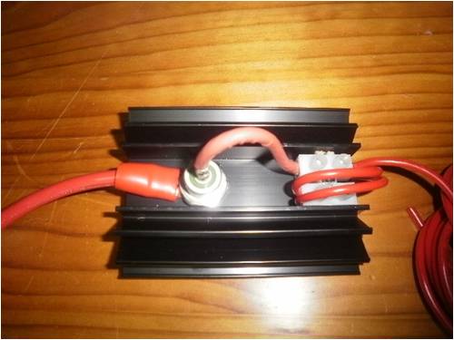
one last thing, this whole thing is going to be "live" do i need to protect it ? obviously I wont mount it onto steel but he wood backing board, I though I'd teck screw it in vertically, is it going to leak to ground? Or electrocute anyone? Luck favours the well prepared |
||||
| Dinges Senior Member Joined: 04/01/2008 Location: AlbaniaPosts: 510 |
KarlJ, If it were mine I'd try to find another connection block, of the ceramic type. After having seen some dramatic pictures from RossW, where such a block nearly melted completely away and came scarily close to shorting things, I'm very suspicious of them when I use them now, especially in high-current applications. Or perhaps use AMP Certicrimp connectors? They're pretty reliable joints, when made properly. At least make sure your screws are tightened well; a little contact resistance will cause heating, more contact resistance, etc., in a runaway process, until you're left with a molten blob of plastic. Ceramic or phenolic blocks may be better, but are harder to find. I'd also find something else than a wood panel to mount it to. Wood and heat don't go together well, I'd be worried about something heating up more than it should and starting a fire. Steel would do, but then have to insulate the diode. Phenolic board (about 6-8 mm thick) would be fine, I expect. Peter. |
||||
| Downwind Guru Joined: 09/09/2009 Location: AustraliaPosts: 2333 |
Hi Peter/Karl, Yes Peter i also agree with you on terminal blocks but think the matter runs a little deeper. The only reason we get heat as you mentioned is resistance, and with screw terminals this is often due to the screw cutting the strands of wire and spreading the strands. Or should we say a poor connection. If one adopts the practice of twisting the strands tight and soldering the exposed wire end before inserting it into the screw terminal than the resistance will not be such a large problem with time. Hence nor will the temp. problem. The theory of bare it back and shove it in, then do the screw up... has more draw backs than often realized. Undo the screw and remove the wire and see how many strands fall off, as well as look at how much of the copper conductor was actually in tight contact. Then add in a few years of oxidation of the connection and you have a high resistant connection. Hence a terminal melt down. I also thought the same about the wooden mounting board Karl used. Here in Oz we have a fibro sheeting called Hardi board or the replacement to asspestos. A sheet of this over the wood panel would give a very good insulator to heat/fire and also non conductive. I just didnt have the heart to tell Karl after all the work he put in setting everything up. Pete. Sometimes it just works |
||||
| Dinges Senior Member Joined: 04/01/2008 Location: AlbaniaPosts: 510 |
[quote]If one adopts the practice of twisting the strands tight and soldering the exposed wire end before inserting it into the screw terminal than the resistance will not be such a large problem with time. Hence nor will the temp. problem. [/quote] Soldering/tinning the wires before inserting them into a choc block is actually a very bad practice. If you want to prevent the wires from being cut by the screw, put a 'cable sock' over it. (not sure what they're called in English; basically a piece of thin tube you slide over the exposed wires, to prevent damage from the screw end) Note that the better choc blocks already have a piece of metal or tab in them that prevent the screw from directly touching the exposed wires anyway. [quote]Undo the screw and remove the wire and see how many strands fall off, as well as look at how much of the copper conductor was actually in tight contact.[/quote] Fully agree with you there! I normally use these 'socks' too - it's a tiny detail, but it makes the difference between a professional job and something my grandmother would do. [quote]I just didnt have the heart to tell Karl after all the work he put in setting everything up.[/quote] I have no problems with saying it to him. 
In fact, I'd want people to point out things they see in my work that could be improved upon - personally, I value criticism, and don't see it as a direct attack on my person. (not suggesting that KarlJ does, though!) The difference between a job that is done 'good' or done 'professional, practically perfect' is usually only slightly and consists of details (like cable socks, cable lacing, heat shrink tube, neat routing, layout, etc.) And personally, I get a very good feeling when looking at a job done properly, either by myself or others. Peter. |
||||
| Downwind Guru Joined: 09/09/2009 Location: AustraliaPosts: 2333 |
Peter once again you are very correct. The point of tinning the wire ends is a case of the two evils (unless you have cable socks). DC cable is often made up of fine stranded multi strand cable that gets destroyed with the screw terminals as we both agreed. I still think tinning the ends is the lesser evil and would prefere it to not doing nothing and the screw cutting into the cable. I seen this a lot with low voltage garden lighting. 400 watt 12 volt systems would burn out the terminal blocks. It was always the connections with loose stranded ends. The connections with tinned ends never gave a problem. As you rightly pointed out cable socks and good quality terminals are a better option, but this is not always the case of what we have to work with. At least with a tinned end you can torque that sucker down tight without destroying the conductors. Pete. Sometimes it just works |
||||
| GWatPE Senior Member Joined: 01/09/2006 Location: AustraliaPosts: 2127 |
If you try and buy cable socks, you will probably get a blank expression from the sales person. I believe the items are normally called "boot lace ends" Gordon. become more energy aware |
||||
| KarlJ Guru Joined: 19/05/2008 Location: AustraliaPosts: 1178 |
OK so I've mounted the diode and the shunt on some cement sheet, do I need to protect them from people touching them? Human body resistance varies from 1000 Ohms to 100,000 Ohms (wet fingers open wounds vs normal dry skin) an it takes 10mA to cause pain thus 60x60/ 1000 =3.6W /60= 0.06A thus I guess theoretically could give you a lethal shock at 60mA, if you touched it with wet fingers and were standing in a puddle of water.... Any ideas for a box?, obviously the heat sink still needs to dissipate heat thus fully enclosed defeats the purpose. Luck favours the well prepared |
||||
