
|
|
Forum Index : Windmills : Old Dunlite Wind Generator
| Author | Message | ||||
Darren Newbie Joined: 13/07/2008 Location: AustraliaPosts: 20 |
Thanks Don for the information on the weights, heavier than expected. My machine is 48 Volt but it is a AC machine brushless so a ohm reading will be no good to you sorry. Darren |
||||
| Smart Drives Senior Member Joined: 06/07/2009 Location: AustraliaPosts: 115 |
A friend of mine has one aswell, I'll find out the specs on his. Cam. All smart drive parts sold Custom built turbine parts on Multicam flatbed CNC Router |
||||
Bergen Newbie Joined: 19/02/2008 Location: AustraliaPosts: 19 |
With that gear ratio it means it is a model L generator, 1000 watts max. or a max of 15 amps if it is a ex PMG unit, Max voltage of 66 volts. The M models had a 5:1 ratio @ 1500 watts output. I've got 4 complete Dunlites and various spares. Don't be tempted in letting the generator put out more than 15amps continously (even thu they can easliy do it) otherwise you will eventualy burn out the armature Wind powers my house |
||||
| Windy Newbie Joined: 04/03/2010 Location: AustraliaPosts: 2 |
6351267 Its good to see someone else who appreciates some really good technology, machinery built to last. I have been using Dunlite 32volt wind plants for 25 years to power my home and farm workshop,lights, 32v drills, welders, grinders etc ........Great stuff AS TAKEN FROM MY DUNLITE MANUALS The easiest way to identify your generator Model M has 5/16 woodruff key and 3 wire terminals ....Model L has a 1/4 inch woodruff key and three wire terminals... model 750 watt has a 1/4 inch woodruff key and 2 wire terminals... PROPELLERS Model M 3 blades Model L 3 blades Model 750 watt 4 blades ..Also some had 2 blades carved out of one plank of wood. VOLTAGES Model 750 watt normal voltage 32v max 50v max amps 20 Model L normal voltage 50v max 66v max amps 15 Model M normal voltage 50v max 66v max amps 23 Model M can run at 110v up to 145v max and max 11amps Cheers Windy |
||||
b351267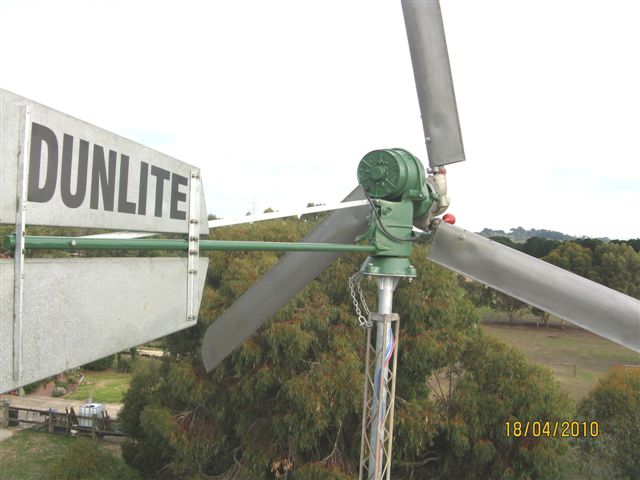 Newbie Joined: 08/02/2010 Location: AustraliaPosts: 27 |
Hi Windy, Thanks for the info. I also have found some other ways now of identifying these machines: Model L and the 750 watt gearbox has a 3.5:1 ratio (Mine is an L) The Model M gearbox has a 5:1 ratio. The 750 watt unit has a dual field winding, accumlulative compound connected and does not require a voltage regulator. The models L and M have a single field winding which is shunt connected via a voltage regulator. The only thing I haven't been able to find out is the field and amature resistances for the different voltages for each model, I would think they would have to vary according to the voltage it is designed to generate. For some reason nobody with a model L that definitly knows its voltage can get out their multimeter and measure the field and armature resistances for me. Even the figures for a 32 volt would help by process of elimination. I am slowly getting mine ready to put up on the tower, I have just developed and built a voltage regulator, very simple and low tech. It is just solid state version of the old mechanical regulator and uses a large diode to prevent reverse current. Regards, Don. Don There is always a 'Plan B'. |
||||
Greenbelt Guru Joined: 11/01/2009 Location: United StatesPosts: 566 |
b351267; Found this, seems to be a installation and maintenance Manual. Google Key words (Dunlite Model (?) History) this is a pdf file with over 60 pages on the Model M. I searched the same site for model L but did not open it. I'm A Caveman with a 56 K modem, long download 2,5 meg. Model L Manual and parts list, L and M Time has proven that I am blind to the Obvious, some of the above may be True? |
||||
| b351267 Newbie Joined: 08/02/2010 Location: AustraliaPosts: 27 |
Thanks for this but I already know about it, it is a site run by Graig Pearen in Canada, http://www.pearen.ca/dunlite/Dunlite.htm I have been in touch with him a number of times and I actually provided him with the scanned copies of the manuals for the L & M he has on his site. His site is excellent and is about the only source of information available, there is virtually nothing in Australia which is strange when you consider they were made and used here in their 1000's. Graig is quite an authority on the later brushless machines but knows little of the older dynamo type like mine. Unfortunatly the manuals have no technical specification such as feild winding resistances etc. so I am still hoping someone can take some measurments of theirs for me. Regards, Don. Don There is always a 'Plan B'. |
||||
| Bergen Newbie Joined: 19/02/2008 Location: AustraliaPosts: 19 |
I've finally got over to the where the old Dunlites are. The measurements here are from two Model L units, both 32volts. The field windings were 27.1 ohms and 27.2 ohms (measured from the field terminal to the negative terminal under the weather shield)The armature resistance on both was 0.4 ohms (measured on the copper communicator itseft at the brush positions) Don't measure the resistance thru the brushes as it will vary. (pending brush used, reliablity of the contact with the comunicator, electrical contact of brush retaining screw etc) The readings are reasonably accurate(Agilent mulitmeter)Some cheaper mulitmeters may not read to accurately at this low of resistance and the difference in resistance from a 32 volt unit to a 50 volt unit won't be that different. I suspect that a 50 volt unit would have a field resistance of approx 42 ohms and the armature around 0.5 ohms. Hopefully this will help you. Regards James Wind powers my house |
||||
Downwind Guru Joined: 09/09/2009 Location: AustraliaPosts: 2333 |
It is good you can be bothered to help Don out with some ohms readings and you quote you have a good meter, as a course of measure, if you could also quote what you meter was set to (200 ohm) when the reading was taken as well as a ohm reading with the leads shorted together. As many meters dont read zero with shorted leads on a low ohms setting it allows for some indication of an actual true low ohm reading. In many cases the reading taken, minus the shorted lead reading is very close to the true ohm reading. This works both ends as the person checking their windings against your windings in ohms should do the same test with their meter and subtract any difference from their readings. This is only advisiable on the low setting on a ohms meter when reading low ohm tests. Still good on you for posting the data and you guys should start another thread with just the raw data on the Dunlite, so it is easy to find and it not get lost in this lengthy thread. It will help others that is in the same boat as yourselves. Just agree on the facts and put a thread together with all the data and links etc in one place. Glenn might even put a link to it from the front page. Be best to keep it as an artical rather than a discussion. There seem to be a reasonable group of you with dunlites and am sure there is many more out there looking for data. If it ends up with a front page link than Google will pick it up and it will show in google searches. It be worth doing guys. Pete. Sometimes it just works |
||||
| b351267 Newbie Joined: 08/02/2010 Location: AustraliaPosts: 27 |
James, Thanks, this is exactly what I need to know, I am now confident mine is a 48 Volt machine. You are not far off the mark with your resistance estimates, the field is 49.1 ohm and bettween the two 90 degree opposing cumutator segments I get .6 ohm. I have subtracted .2 ohm for the resistance of the leads and probes of my Fluke multimeter. Pete, I certainly agree with your comments re low resistance measurments, however the measurments from James are accurate enough to to tell me what I need to know. Silicon Chip magazine recently published a design for a 'low ohms adaptor' to use with a multimeter, it works on a similar principal to the old Wheatstome Bridge which I am familiar with from my early Telstra (PMG)days when we used them for locating cable faults. I had intended to eventualy publish what data I have as you suggest, I will probably ask Graig Pearen if he will put it on his website, (see my March 5th post), unfortunatly I still don't have lot, just these resistance measurments and the gear ratio differences bettween the models L & M, perhaps other people will provide me with more data. I would suggest a link to the Pearen site from the front page would be best. Regards, Don. Don There is always a 'Plan B'. |
||||
| Bergen Newbie Joined: 19/02/2008 Location: AustraliaPosts: 19 |
Hi Pete and Don, The meter was on the 200 ohm scale (lowest range it had) and it actual reads 0.0 ohm when shorted. This is a new meter and was calibrated by Agilent January this year. When I received the meter, the low ohms scale was checked against the Lucent low ohms meter that we use to make shunts and loads with and was within 0.05 ohm of it. The lucent meter reads down to 0.0001 ohm. I would have used it except it needs 240ac power and there is no power where the dunlites were. Don, lucky you had also had a good meter and with your resistance readings it looks definitly that you got a 48 volt machine. Its great to see someone else getting these machines going. We should get the info together and post it somewhere as there is still a lot of them out there. The orginal info, data and parts was distroyed by the new company that brought out Dunlite (they only wanted the power generation side of the business). James Wind powers my house |
||||
| neil0mac Senior Member Joined: 26/12/2009 Location: AustraliaPosts: 210 |
A very early version? Found the serial number --- 1762. Two wired, geared head, with -20 to +20 DC Ammeter, so that says it the 32V version? Right/wrong? Now, there is an additional bit - a voltage regulator(or other?) appears to be a later version (rather less weathered with plastic covered wiring rather than cloth) with capacitors etc. but it does say 'Phillips 20 AMP 8824" on one of the covers covers (each attached by two screws) on the outside. The other cover appears to have '750' (plus other undistinguishable markings) on it. It has six wires (3 red, 3 black) coming out of it. There is nothing to say where are these attached - as there is no wiring diagram in the manual. Thanks. |
||||
| b351267 Newbie Joined: 08/02/2010 Location: AustraliaPosts: 27 |
Neil, I have little knowledge of the 750 watt machine as I don't have one nor have I seen one, however I would say that all of your asumptions are correct. The 'additional bit' you refer may be a mechanical 'cutout relay' or a seleniem rectifier. It's purpose is to prevent reverse current flowing back through the armature and field windings when the battery voltage exceeds the voltage level the generator is producing. If you look at page 10 of the manual (Pearen site), it explains where the 6 wires go. This model did not use a voltage regulator, but instead relied for regulation on compound connected field windings, unlike the later models L & M which have a single shunt connected field winding and use a voltage regulator. The seleniem rectifier is the predesessor of today's diode. You could probably replace your cutout relay with a heavy power diode as I am doing with my machine. Regards, Don. Don There is always a 'Plan B'. |
||||
| Bergen Newbie Joined: 19/02/2008 Location: AustraliaPosts: 19 |
Hi neil0mac, The turbine you have there is most likely a 750 watt, 32 volt (you will have a 4 blade fixed pitch prop?) with a later version voltage regulator. The wires are 2 from the turbine, 2 for the battery and 2 for the load. This is the link for the turbine manual http://www.pearen.ca/dunlite/32v/32v750wGearDriveManual.pdf .You should find most of the info reqired in this manual (wired the same as the old regulator, read under the heading of RELAY)You will have to identify which is the B, G and L wires A connection diagram can be found in the model L/M manual from the same site (ignore the power control unit in the diagram. This is used on field controlled turbines) The other method is do what most of us are doing nowdays is to just connect the turbine to your battery bank via a large diode (at least 40amp) and use a shunt regulator to regulate. James Wind powers my house |
||||
| b351267 Newbie Joined: 08/02/2010 Location: AustraliaPosts: 27 |
My Dunlite Model L is finally up and running, however I still have some blade balance issues. I havenot had a decent wind yet to test it properly but early indications are good. See attached photos. 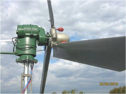
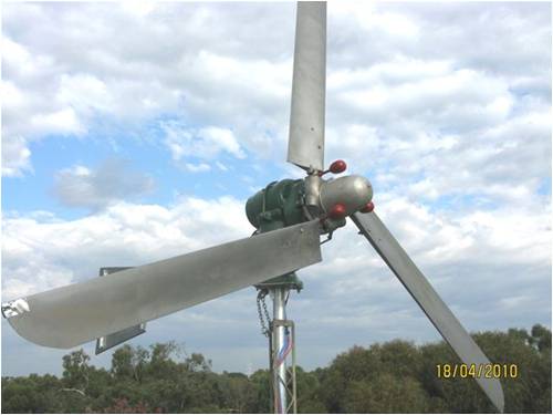
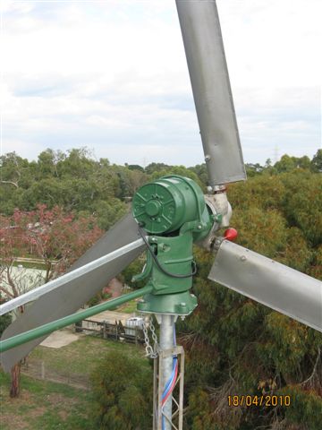
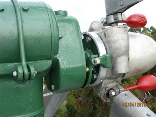
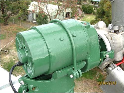
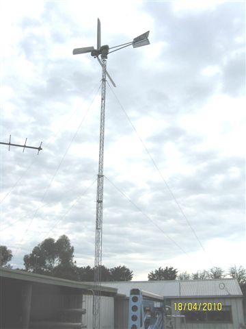
Don There is always a 'Plan B'. |
||||
| b351267 Newbie Joined: 08/02/2010 Location: AustraliaPosts: 27 |
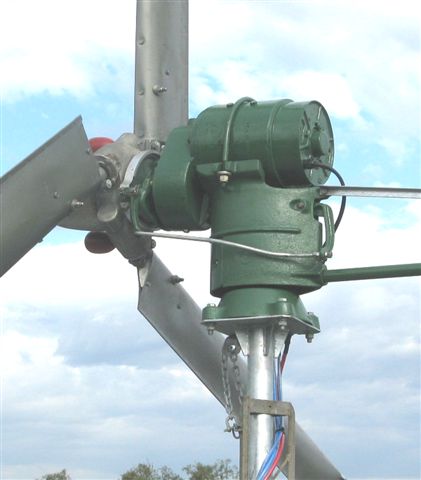
Another pic showing art work on the tail, it is the same on the other side but with the artwork slope reversed. If enough people are interested, I can have more made, price depends on how many. 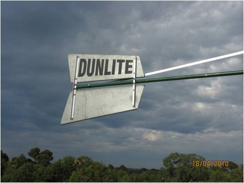
Don There is always a 'Plan B'. |
||||
| philb Regular Member Joined: 05/07/2008 Location: United StatesPosts: 96 |
That is a beautiful machine Don. Thanks for posting the pictures. philb |
||||
luxman68 Newbie Joined: 01/10/2010 Location: AustraliaPosts: 1 |
Hi , you may have already ballanced your props but if you havent, some friendly advice. Many people used screws and washers for ballancing as well as other methods of ataching weights. I have found , tinning a section of each blades trailing edge and then soldering or lead wiping that section a much better way. Once the solder or lead is in place it can be filed to adjust each blade individualy. If you are going to be playing with the dunlites ( and I hope you stay with them ) building a ballancing stand , using the gearbox casing from a scrapped unit will prove an invaluable tool in years to come. These Dunlite units are by far the best wind turbine units ever made I.M.O. They are relliable require almost zero maintenance and the squeek of a correctly set ( timed ) brush set is a sweet sweet sound. Hope you have as much fun as I have had over the years and continue to have today. Cheers, Charlie |
||||
| b351267 Newbie Joined: 08/02/2010 Location: AustraliaPosts: 27 |
Charlie, Thanks for your advice on balancing, I only wish I had known or thought of lead wiping when I had the blades off. My solution was small strips of lead pushed up the joint at the propeller tips with a self tapper through to stop them flying out. Nowhere near as elegant or aerodynamic as your method. My blades are now reasonably well balanced but not as good as I would like them to be. The method I used was to mount each one on a piece of 1" pipe, suspended from the ceiling with a weight at the opposite end. Starting with the heaviest blade, using a spirit level, I then added weight to the opposite end of the pipe until it hung perfectly level. I then substituted the other two blades using the same weight at the opposite end, then added weight to the blade tip until each hung level. I really believe that to get them perfect I need to balance them on the hub as I believe the hub has imbalance also. The only way I can think of is similar to the way they balance wooden aircraft props, they mount them on a shaft with the shaft sitting on knife edges to eliminate almost all friction, then they adjust the weight of the blades until the prop will sit in any position. The problem doing this with the Dunlite prop is that I can't think of a way of extending a shaft through the front of the hub, or any other way of mounting it to eliminate all friction. The ultimate way of course is to do it dynamically, but it would be a big job to build a rig to do this. You mention brush timing, unfortunately I don't know how well mine are timed as I had no way of driving it on the ground while observing the commutator, it does however squeak rhythmically at low speeds but I am not sure if this is good or not. Overall I am quite pleased with its performance and it is now driving two SWEA grid connect inverters and doing something useful. In fact I have been known to sit watching it spin in the sea breeze for long periods of time while enjoying a beer/s on a nice summer evening. Don. Don There is always a 'Plan B'. |
||||
| Robb Senior Member Joined: 01/08/2007 Location: AustraliaPosts: 221 |

Are you sure that tower mounting is strong enough? |
||||
