
|
|
Forum Index : Windmills : Old Dunlite Wind Generator
| Author | Message | ||||
| dwyer Guru Joined: 19/09/2005 Location: AustraliaPosts: 573 |
hi Charlie l do agree with Robb over tower mounting look that you using 3 mm plate and support frames is to small and too short maybe you might overlook your design. maybe should go on 6 or 8 mm steel plate will help? 
Dwyer |
||||
| GWatPE Senior Member Joined: 01/09/2006 Location: AustraliaPosts: 2127 |
Hi, I have to agree with Dwyer and Robb re the attachment you have shown a pic of. An indication of the flange thickness required is given by the flange on the Nacelle. Ideally a similar thickness on the tower would be on the money. The mounting you have shown would be fine however on a test pole outside your workshop, that would be used to support the mill for checking blade balance etc.. These older wind turbines are nostalgic and it would be a shame if the flange failed and it all ended at the tower base. Good luck with your efforts. Gordon. become more energy aware |
||||
b351267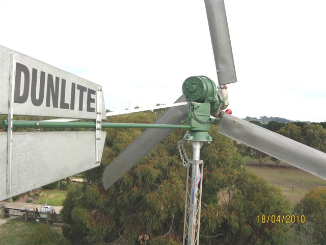 Newbie Joined: 08/02/2010 Location: AustraliaPosts: 27 |
Looks can be deceiving, the pipe is medium gauge steel, also the mounting flange is gusseted and the whole thing professionally welded and hot dipped galvanised. The tower is also very light, it is just an old antenna tower but the way it is guyed allows it to flex a certain amount relieving much of the strain at the mounting. I am used to working with aircraft structures where things are light but strong. you will however also notice the chain 'just in case'....... Don There is always a 'Plan B'. |
||||
| dwyer Guru Joined: 19/09/2005 Location: AustraliaPosts: 573 |
Hi Don first for all sorry for spelling wrong name so anyway back to the mounting flange is gusseted so  l am afraid doesn�t sound right to me so this use tower design for antenna however you got beauty Dunlight wind generator carried more weight than antenna sitting thin steel plate with chain hoping will not come off including welded to pipe and if this fail and snap off and risk a lot of damage to Dunlight so why take the risk if l were you is replace thicker steel material and workshop quality done properly is peace of mind same to Dunlight wind generator l am afraid doesn�t sound right to me so this use tower design for antenna however you got beauty Dunlight wind generator carried more weight than antenna sitting thin steel plate with chain hoping will not come off including welded to pipe and if this fail and snap off and risk a lot of damage to Dunlight so why take the risk if l were you is replace thicker steel material and workshop quality done properly is peace of mind same to Dunlight wind generator 
hope that make sence. Dwyer |
||||
| Frango Newbie Joined: 16/10/2010 Location: AustraliaPosts: 2 |
Great thanks to WINDY for your info in the quote below. Your info will tell me what it is and maybe(??)get it rewound for 48V if it is 32V. Dont remember seeing this kind of info in my handbooks that will be dug up soon. I'm planning to resurect an old Dunlite I've had for 30 years. Noticed the smaller gears are quite worn. (2 inches dia.) Frango |
||||
| b351267 Newbie Joined: 08/02/2010 Location: AustraliaPosts: 27 |
The following may also help, it is all contained in previous posts on this topic. The Model L and the 750 watt gearboxs have a 3.5:1 ratio (Mine is an L) The Model M gearbox has a 5:1 ratio. The 750 watt unit has it�s fields windings accumulative compound connected and does not require a voltage regulator. The models L and M have their field windings shunt connected via a voltage regulator. Resistances for the model L are as follows: 32 volt machine: Field 27 ohms Armature 0.4 ohms 48 volt machine: Field 50 ohms Armature 0.6 ohms Measure the armature resistance directly on the 180 degree opposing segments on the commutator, not at the brushes. Suggest also that you check out the Pearen site: http://www.pearen.ca/dunlite/Dunlite.htm Don There is always a 'Plan B'. |
||||
MacGyver Guru Joined: 12/05/2009 Location: United StatesPosts: 1329 |
General Question Anyone know what the three little red weights are for? At first, they reminded me of the weights on the Jacobs wind turbines, which actuated their controllable-pitching mechanism, but on closer examination of both the photos and that hand-drawn dimensional picture, I can't see how they'd work to accomplish twisting the blades, let alone doing it synchronously. . . . . . Mac Nothing difficult is ever easy! Perhaps better stated in the words of Morgan Freeman, "Where there is no struggle, there is no progress!" Copeville, Texas |
||||
| windlight Guru Joined: 03/03/2007 Location: AustraliaPosts: 331 |
Mac they are the weights for the centrifugal governor, look around here http://www.pearen.ca/dunlite/Dunlite.htm one of the biggest problems with the Dunlite governing system in my observation is that those weights were held to the blade shaft by an aluminum clamp, which occasionally broke, resulting in massive out of balance and tower down syndrome. allan "I like this place and willingly could waste my time in it" - (Act II, Scene IV). |
||||
| MacGyver Guru Joined: 12/05/2009 Location: United StatesPosts: 1329 |
windlight Thanks. I looked through the site, but found no schematic as to how it worked except something explaining the torque. I still don't see how three independently-pitch-governed blades would work together in unison; maybe they don't, I dunno. At any rate, thanks for the reply. . . . . . Mac Nothing difficult is ever easy! Perhaps better stated in the words of Morgan Freeman, "Where there is no struggle, there is no progress!" Copeville, Texas |
||||
| Frango Newbie Joined: 16/10/2010 Location: AustraliaPosts: 2 |
Hi all Dunlite enthusiasists. Craig Pearens info page is great and I emailed him with the info below but since he has had spam problems, his address doesnt exist. I hope Craig sees this, OK but surely someone can give this to him to help one another? This is what was returned to me. Cheers Frango Hi Craig Very well done your manuals I found on your web site. You say that page 2 and 3 are missing on the 32V 750watt manual. I have that one and I can assure you that those pages are exactly the same as the L & M manual. I have that one too but I still checked against your pages. Cheers Frango |
||||
Jarelbee Newbie Joined: 02/09/2011 Location: AustraliaPosts: 4 |
In the factory the balancing of blades was done on the hub mounted on a platform in a draft free area of the factory. The blades were allowed to find their own balance with the heaviest one always ending up at the bottom. The lichtest blade would always find the highest point. pieces of sheet metal would be inserted into a not yet spot welded section towards the tip on the skin. This proceedure was repeated until when the hub was rotated it would not stop in the same place each time. This was a very crude but effective method of static balancing. When the blades were in a state of balance they would be taken back to the sheet metal dept and the balance weights spot welded in place. (when I first started working at Dunlite in 1971 at the old original Frome Street Adelaide factory they had an enormous evaporative air conditioning system developed by Lloyd Dunn and mid summer there was almost a rebellion whenever prop blades were balanced as the A/C had to be turned off). 14 years at "Dunlite" last 7 running the wind driven generator section. |
||||
| Gizmo Admin Group Joined: 05/06/2004 Location: AustraliaPosts: 5012 |
Thats a interesting story Jarelbee, its good to hear from people who actually built the Dunlites. Thanks for sharing. Glenn The best time to plant a tree was twenty years ago, the second best time is right now. JAQ |
||||
| Jarelbee Newbie Joined: 02/09/2011 Location: AustraliaPosts: 4 |
That is almost the same as my old favorite saying.... Patience.... Perseverance and a four pound hammer. Happy to help where I can with any info I can drag up on the old dunlite stuff... been a long time now since (1985) and a lot of water has gone under the bridge since then. 14 years at "Dunlite" last 7 running the wind driven generator section. |
||||
| Jarelbee Newbie Joined: 02/09/2011 Location: AustraliaPosts: 4 |
The individual propellor blade shafts are controlled as a group by a small lever protuding at right angles from each shaft towards the centre of the hub. (shafts are tangential to the centre of the hub) These lever arms have a wheel on the inner tip. The wheels locate in a groove in the movable (sliding) central governor. The sliding governor is located on the central (fixed) spindle of the hub and pre tensioned by a adjustable spring protruding to the front of the hub. (the governor is also dampened by minature oil filled shock absorbers) Each Blade shaft when the blades are fitted has a counterweight fitted in an offset manner. The centrifugal counterweights react when the revolutions reach a set speed, causing the blade shafts to rotate (as a group) controlled by the 3 lever arms with the wheels in the groove of the central sliding governor. This causes the blades to feather, controlling the maximum speed. This design was the result of research carried out by Lloyd Dunn and Pat Robilliard (Robbies Arial Services). 14 years at "Dunlite" last 7 running the wind driven generator section. |
||||
Dragonfly Newbie Joined: 25/06/2011 Location: AustraliaPosts: 17 |
Hello Jarelbee, I have recently bought a damaged Dunlite "Model L" with the intention to restore it. The generator itself is in rather good shape thanks to its robust design and built. Unfortunately, the three propeller shafts are bent due to a massive fall from height. Only two of the three governor weights are in my possession. After drowning the pitch control hub in WD40 overnight, and followed up by persistent, sometimes brutal, hammer work, I have managed to free the shafts from the hub. The aluminium propeller base is firmly attached, almost welded to the steel shafts. I want to separate it from the steel shafts before the shafts can be straightened, presumably by heat treatment. With your vast working experience with the Dunlites, what do I need to do to separate them. Thank you Waste not... |
||||
| Jarelbee Newbie Joined: 02/09/2011 Location: AustraliaPosts: 4 |
I would say that heat treatment would be the best way to go as the expansion rate of aluminium is far greater than that of the steel shafts. we used to use a crayon to mark the aluminium with before heating it (thermochrome I think) it changed colour well before the aluminium reached melting point. I am not sure of the temperature we used now as it has been at least 25 years since I was involved with them... Just take it easy and see how it goes... we used to use an LPG tourch to do this task.. I hope that will help you "DO NOT QUENCH THE ALUMINIUM IN WATER TO COOL IT AS IT WILL CRYSTALISE AND DISTORT" 14 years at "Dunlite" last 7 running the wind driven generator section. |
||||
| Dragonfly Newbie Joined: 25/06/2011 Location: AustraliaPosts: 17 |
Hello Jarelbee, Thank you very much for your prompt answer. One of the aluminium blade bases was already damaged by the fall. Its governor weight attachment was sheared off. I am thinking of ... 1. Discarding the aluminium bases altogether, 2. Building a set of wooden blades attached to a set of blade base similar to the ones built by member Fillm here. 3. Since I only have two of the three governor weights, I may need to build a new set using some heavy pipes equivalent to the weight of the originals. Any suggestions would be most appreciated by me. Thank you again. Waste not... |
||||
| windlight Guru Joined: 03/03/2007 Location: AustraliaPosts: 331 |
Dragonfly, The third weight broke in service at the aluminum clamp and flew away never to be found, the resultant imbalance brought the whole tower down all 40' of it. For what it is worth I recommend retaining the aluminum blade bases, I know this will require some perseverance but it be rewarded in the long run. Replicating the original weight would be a better option than making pipe ones, the distance each part of the weight is from the center and their blade shaft affects the governing, although having said that I suspect the adjustment on the spring may adequately compensate. My recommendation was to replace the aluminum clamps that hold these weights. Allan "I like this place and willingly could waste my time in it" - (Act II, Scene IV). |
||||
Madness Guru Joined: 08/10/2011 Location: AustraliaPosts: 2498 |
This thread brings back some memories, I had a 1500 watt Dunlite. Only problem was the rollers in the end of the forks in the governor system kept flogging out due to turbulence. Even though it was up an 80 foot tower it was hit with an updraft through the trees. In the photo the trees to right where the problem the big one on the left was well below the generator. The photo was taken with 15 second exposure about 30 minutes after sunset. 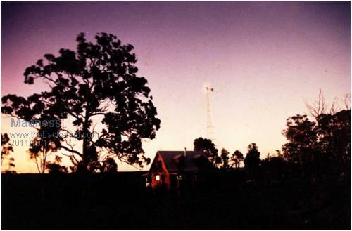
There are only 10 types of people in the world: those who understand binary, and those who don't. |
||||
| b351267 Newbie Joined: 08/02/2010 Location: AustraliaPosts: 27 |
Sadly my Dunlite model L is no more, snapped a guy wire today and the whole lot came crashing down! Damage is pretty catastrophic, about the only thing that survived unscathed was one blade and the dynamo itself. I have no desire to try to source parts and repair it so the remains are available to anybody who can use them, the sooner I don't have to see it anymore the better.... Don. Please note that you would have to pick it up from Geelong. 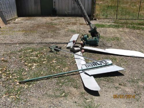 Don There is always a 'Plan B'. |
||||
