
|
|
Forum Index : Electronics : Op-amp charge controller
| Author | Message | ||||
| adonis Regular Member Joined: 13/02/2010 Location: SwedenPosts: 42 |
hello. this might be the wrong place to post this? I am trying to understand the basics of the controller, and I have a question: the OP1 is swiched on when the voltage drops below 12V, turning OP3 of (closing the transistor and disconecting the dump load). but when the voltage rises again, and gets higher than 12V the OP1 is swiched off. what makes the OP3 stay off? this is not my area of expertise, so there might be a very simple expanation, but the slightest voltage fluctuation seems to be able to turn OP3 on, and since it is connecting to itself through a loop it would stay on? am i on to something or am i just stupid? /jonathan |
||||
Downwind Guru Joined: 09/09/2009 Location: AustraliaPosts: 2333 |
Bob, i would like to see a pic of your work. I dont think George will get confused knowing it is your layout. You must find the circuit very practical to be on your 4th one now. By all means post some pin voltages as it will help to answer some others questions to. Think i will still build one as its only a 15 minute circuit to construct and i have all the bits handy except the 8 volt reg. That way i have something to cross check others results against too. Pete. Sometimes it just works |
||||
| Bub73 Senior Member Joined: 10/12/2009 Location: United StatesPosts: 116 |
Welcome adonis; I'm still trying to get my head wrapped around this op amp also. @ Pete I'll get some new pics and data from this one first of the week, I just had to relocate the 100k on this board so its changed from my current pics but should be ready to smoke test. Looks like a busy weekend here or I'd do it sooner. Bob |
||||
oztules Guru Joined: 26/07/2007 Location: AustraliaPosts: 1686 |
[quote]OP1 is swiched on when the voltage drops below 12V, turning OP3 of (closing the transistor and disconecting the dump load). but when the voltage rises again, and gets higher than 12V the OP1 is swiched off. what makes the OP3 stay off?[/quote] Answer, the 10k resistor is holding the non-inverting input low on op-amp3. Now Op amp 3 was previously held low by op amp 1, 10k now softly latches it still low... ie holds it low (pos feedback) unless a lower impedance high is placed on it's non inverting input...(swamps it) it would then swing high and the 10k helps sort of latch that too. When both inputs of op amp 3 are the same (both low in this case), the difference is close to zero, so the output is the gain X this difference which is apparently less than the voltage on non-inverting input of opamp 4 (4k7 divider =6v?..... so bd139 stays off. ......oztules Village idiot...or... just another hack out of his depth |
||||
| adonis Regular Member Joined: 13/02/2010 Location: SwedenPosts: 42 |
When both inputs of op amp 3 are the same (both low in this case), the difference is close to zero, so the output is the gain X this difference which is apparently less than the voltage on non-inverting input of opamp 4 (4k7 divider =6v?..... so bd139 stays off. ......oztules yes, but it is here my concern lies, even if the difference (lets call it Ua-Ub, where Ua is OP3 +input and Ub is OP3 -input) is close to zero, the output might be >6V. if i am correct, the OP-amp is in the ideal case amlpifying this differrence indefinate, and in real cases the amplification (lets call it F) is around 10^5. if the OP4-input=6V (i think it is 8V/2=4V, but lets use 6V) then it would be enough with (Ua-Ub)> 6*10^-5 = 0,060mV to trigger OP4? and that is close to zero... but as i said, im not an expert on cicuits. and if lots of people has built this controller successfully, surely someone should have noticed if the dump load is connected too early in the chargeing process. is this nothing to be concerned about? /jonathan |
||||
| oztules Guru Joined: 26/07/2007 Location: AustraliaPosts: 1686 |
Yes, I didn't look at Vcc, and wrongly assumed 12v... didn't look at the reg 
The gain in the configuration. With pos feedback of 10k, we would normally see 10k/series input resistance I think. The Tl084 has 200R seriesed on the output,( and another 100R through the transistor to ground..... both internal). I suspect this gives us a gain of 10000/300=33 or 10000/200=50 at best. This may explain why it does not get to the 4v required to throw the next stage out. This enables the 10k to continue to latch the output off. A different op-amp like the 324 may not work well in this case, as it will only have transistor closed to ground... with no series resistance. Your thoughts? ..........oztules Village idiot...or... just another hack out of his depth |
||||
| GWatPE Senior Member Joined: 01/09/2006 Location: AustraliaPosts: 2127 |
This discussion seems to be missing the importance of the diode, in the output of OpAmp2. OpAmps are not anything like logic components. even if Amp1 and Amp2, are both low, or both high, There will still be a significant voltage between the inputs of Amp3 because of the diode. I work the first stage circuit functions as just 2 comparators. One is activated when the voltage between inputs increases, and the other activates when the voltage between inputs decreases. Amp3 gives extra gain, hysterisis and positive logic for the indicator. Amp4 is a digitising buffer. Any problems with the cct will be related to construction. I would change the trimmers to a lower value, or substitute for multi turn types, to make the setting easier. As with any cct that has hysterisis, setting up is sometimes tedius. Gordon. become more energy aware |
||||
| oztules Guru Joined: 26/07/2007 Location: AustraliaPosts: 1686 |
[quote]This discussion seems to be missing the importance of the diode, in the output of OpAmp2. OpAmps are not anything like logic components. even if Amp1 and Amp2, are both low, or both high, There will still be a significant voltage between the inputs of Amp3 because of the diode.[/quote] You had better walk me through this slowly then Gordon. The only relevance I can see for the diode is to isolate opamp2 from closing down op amp3 as we drop below turn on threshold...after we have turned on. I figure it is there to keep the dump on, even though op2 turns off. It (the dump load) should not turn off until op1 fires up to stop it. I fail to see any other part it plays.... but am open to your suggestions on this. I can't see how it is going to provide turn on to op3 after the initial turn on. The 10k keeps it held on without the low from op2 now getting through the diode... it only isolates it after turn on.... doesn't it? I see this as a window comparator. Edit: [quote] Amp3 gives extra gain, hysterisis and positive logic for the indicator.[/quote] The hysterisis is provided by the fact that we have a turn on and a turn off control. The positive feedback on opamp3 is not hysterisis (yes usually if I see a pos feedback resistor, I think hysterisis too). In this case, both inverting and non-inverting inputs are driven by low impedance drivers... about 300R. The 10k is irrelevant in modifying the turn on /off timing. It is purely acting as a latch to hold the amp on after opamp 2 has dropped out. As above, I believe the isolating diode is only there to keep the low impedance (now low) from turning off the opamp3... which is held on at this time by the 10k resistor..... put another way... opamp3 contributes no hysterisis. Hope I explained that adequately for you to trouble shoot me. oztules.... who thought he had it sussed..... but??? Village idiot...or... just another hack out of his depth |
||||
| Downwind Guru Joined: 09/09/2009 Location: AustraliaPosts: 2333 |
This had all got the better of me and started to feel it was going around in circles. With who is right and who is wrong and what works and what dont........................??????? So i constructed the circuit as per how Glenn has shown with the vero board layout hole for hole. One important thing to note i did not have a 8 volt reg so i used a 9 volt reg and adjusted a couple of resistor values to bring the voltages back within the operating range. The circuit worked fine!!!!!!!!!!!!!!!!!!! The red trimmer is the high V, and the blue trimmer is the low V. 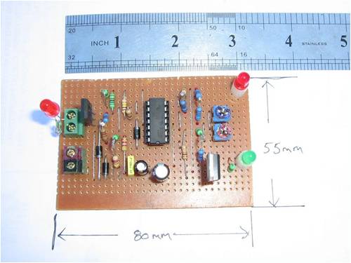
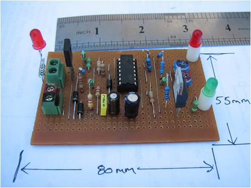
The help with the discussion on threash hold voltages i will list the opamp pin voltages for my circuit but as i am using a 9 volt reg and the pin voltages might be different to others circuits with a 8 volt reg. [code] 12.15 volts supply pin volts 1 1.32 OP1 2 3.42 - 3 2.89 + ---------------- 4 9.00 ---------------- 5 2.88 + 6 2.89 - 7 1.47 OP2 ---------------- 8 1.37 OP3 9 1.47 - 10 1.25 + ---------------- 11 0.00 ---------------- 12 1.37 + 13 4.05 - 14 1.23 OP4 ---------------- 15.00 volts supply pin volts 1 8.20 OP1 2 3.42 - 3 3.41 + ---------------- 4 9.00 ---------------- 5 2.88 + 6 3.41 - 7 1.32 OP2 ---------------- 8 6.90 OP3 9 1.32 - 10 6.24 + ---------------- 11 0.00 ---------------- 12 6.90 + 13 4.05 - 14 7.44 OP4 ---------------- [/code] Note the vero board layout is slightly different to schematic. The actual circuit pinout are as follows. The high V opamp is OP1 (pin 1,2,3) The low V opamp is OP2 (pin 5,6,7) opamp 3/4 is OP3 (pin 8,9,10) opamp 4/4 is OP4 (pin 12,13,14) Also the schematic shows a 12K resistor as R1 and the vero board shows a 10K resistor as R1. I found i needed a 10K resistor as R1 to get the circuit to work in my case. Pete. Sometimes it just works |
||||
| adonis Regular Member Joined: 13/02/2010 Location: SwedenPosts: 42 |
This is a bit above my level of understanding the opamps... You seem to know quite a lot more than me about these things so maby I should stop whining. but I obviously will not. I found a datasheet on the TL084, and found under 'electrical characteristics', that the Avd (large-signal differential voltage amplification) is between 50 and 200 V/mV. Is this not the same parameter as the 'gain' we have discussed? It is good for me to know that different OPamps have quite different characteristics, as I am building a savunius turbine only from scrap. I have found some components in different discarded electronical equipment. currently I am looking at a HA17339 to relpace the TL084, and I'm having trouble scoring a 8V regulator, so I propably will replace that with a L7805cv.. If this might work (Im still pondering and learning) I will work out new resistor values. this circuit is by far the simplest and easiest to understand that I have come across. /jonathan |
||||
| Gizmo Admin Group Joined: 05/06/2004 Location: AustraliaPosts: 5036 |
I've created a monster.  The best time to plant a tree was twenty years ago, the second best time is right now. JAQ |
||||
| oztules Guru Joined: 26/07/2007 Location: AustraliaPosts: 1686 |
Jonathon, I have a suspicion that the HAI17339 is the same as lm339. If so, you have an open collector output, and will require pull up resistors to get any output ... ie it pulls the output to ground, or floats.... but with no output voltage.... so you will have to provide a pull up resistor to give you a high output. I'm not to hot on these things either...... but we struggle on .
My gain figures are compromised (read wrong). I was looking at the non inverting input .... and thinking inverting input..... so I don't know what the gain would be..... but it will be high. .........oztules Village idiot...or... just another hack out of his depth |
||||
| Downwind Guru Joined: 09/09/2009 Location: AustraliaPosts: 2333 |
Jonathan, If it was me i would source the TL084 and not mess with a different opamp as i think you will have trouble getting all the voltages correct to suit the different opamp. The small cost of the TL084 would well be worth the time saved messing with a subsitute. Up to you but this circuit works well when constructed correctly and is simple enough. If you want data sheets try .....http://www.datasheetcatalog.com/ Its a free site and you will find lots of data there. Pete. Sometimes it just works |
||||
| oztules Guru Joined: 26/07/2007 Location: AustraliaPosts: 1686 |
Pete... you have too much energy... We need to know the voltages on opamp3 input pins and output..... at 5 stages. 1. predump voltage.........Below Vhigh before any dumping has been done. 2. at dump voltage turn on (V high) Even going back below this Vhigh, op3 will stay latched via the 10k and the diode isolating the op2 which will now be off again. 3. below dump turn on voltage (V high) but still above (V low)... but dump load still on. 4. at dump turn off (Vlow) and .. tada... what Adonis wanted to know initially 5. the voltage above Vlow, but before VHigh but after turn off and beginning to rise again. This is the time that was queried intially.... how does it stay off. The voltage on the two inputs of op amp3 should tell us something... and thus the output..... Needs to be less than 4v. 6. If your not confused yet.... I'll work harder at it ............oztules Village idiot...or... just another hack out of his depth |
||||
| Downwind Guru Joined: 09/09/2009 Location: AustraliaPosts: 2333 |
Some more Tules food, I have bald spots after this thread. Ok i took voltage reading in 1 volt steps up to dump on and the same in reverse to dump switches off. Readings for opamp3 +,-,Op. Dump on latch voltage set to 15.00 volts and dump unlatch set to 12.15 volts. [code] Forward 12 > 15 11v 12.15v 13v 14v 15v 16v + 1.24 1.23 1.28 1.28 6.25 7.72 - 8.01 8.47 1.38 1.35 1.33 1.32 Op 1.36 1.36 1.41 1.41 6.91 6.94 ------------------------------------------ Reverse 15 > 12 + 1.22 1.26 6.25 6.25 6.25 - 8.47 1.47 1.37 1.34 1.33 OP 1.34 1.39 6.91 6.91 6.91 At 14.9 volt input, + = 1.28, - = 1.35, Op = 1.40 At 15.0 volt input, + = 6.25, - = 1.33, Op = 6.91 The change over voltage for input (-) is 12.15 to 12.17 volt [/code] Well Oz deconfuse me?? Hope its enough information. Pete. Sometimes it just works |
||||
| adonis Regular Member Joined: 13/02/2010 Location: SwedenPosts: 42 |
yes, this is at least enough to satisfy me... thanks for all spent time and for all explanations (all of you!). then i know that the circuit works as it is supposed too. the scrap thing is not only because of money, this project is a part of a bigger one, with the intention to learn villagers in uganda how to build ther own simple wind/water turbines. but i think you (Pete) have a point when you recomend me to stick to the original layout. this will be hard enough for me, as i have never built any citcuits before. regarding the boldness; im sorry, i seem to have that effect on people... well, thanks again. /jonathan |
||||
| Downwind Guru Joined: 09/09/2009 Location: AustraliaPosts: 2333 |
Jonathon, Who is building the boards, you or the villages. How many boards are being built. Trying to work out of recycled electronic bits is a loosing battle and costs more in the long run. Think the TL084 is about Au$2.00 and is rather cheap for the main brain of the circuit. The relay would be the most expencive part of the circuit. If you need some help with building the circuit for the first time than ask, as many here will help with tips of how we do things. We all need to start somewhere to learn, as i think many have with this circuit, hence some of the problems discussed over time. You Mensioned Boldness....What boldness...None of that here.....?? Pete. Sometimes it just works |
||||
| adonis Regular Member Joined: 13/02/2010 Location: SwedenPosts: 42 |
|
||||
| adonis Regular Member Joined: 13/02/2010 Location: SwedenPosts: 42 |
im going shopping for a TL048, bd139 and a 78l08 tomorrow, as you said, its not very expensive. (i scored a relay in a car, looks like new to me). i have a quick question, is a L7808cv the same (or just as good) as a 78L08? im not sure about anything anymore... thanks/jonathan |
||||
| adonis Regular Member Joined: 13/02/2010 Location: SwedenPosts: 42 |
this project is just being started up, and so far im not sure who will do what. but the intensions are that they will build everything themselves, that someone with basic technical skills (and a big pile of scrap) will be able to pull it together. |
||||
