
|
|
Forum Index : Electronics : Op-amp charge controller
| Author | Message | ||||
| kalamidas Newbie Joined: 19/02/2010 Location: GreecePosts: 21 |
i've noticed a bridge betwen 10 and 11 pins,i cut it and THE BOARD WOKS . THANK YOU ALL !!!!!!!!!!!!!!!!!! NOW i can cross referance this one with the first one and i will have a backup board. i will post a photo of the finist controller . AGAIN THANKS TO EVERYONE. |
||||
| kalamidas Newbie Joined: 19/02/2010 Location: GreecePosts: 21 |
PS: IF THE WINDMILL DOESN'T BURN IT ALLREADY :-) |
||||
Downwind Guru Joined: 09/09/2009 Location: AustraliaPosts: 2333 |
Hi kalamidas Yes your voltage readings show where the problem was. Good to hear you have a working board after all the time you have put in. Errors are easy made even with the best of us. Pete. Sometimes it just works |
||||
| kalamidas Newbie Joined: 19/02/2010 Location: GreecePosts: 21 |
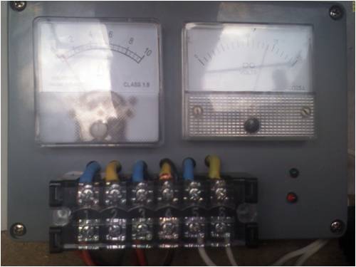
this is finally my controller up and running it dumps at 14.6v and stops at 13.4v 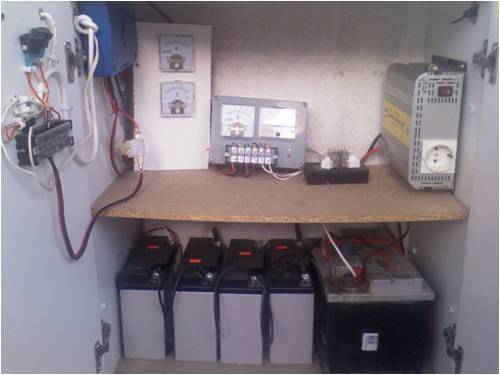
Now i need a dump load for my setup but i believe i must go to an other thread. Again thanks for your help.without your help i'll probobly give up. |
||||
| Gizmo Admin Group Joined: 05/06/2004 Location: AustraliaPosts: 5032 |
Glad to see you got it sorted out. Nice looking set up. Glenn The best time to plant a tree was twenty years ago, the second best time is right now. JAQ |
||||
| adonis Regular Member Joined: 13/02/2010 Location: SwedenPosts: 42 |
is it a good or bad idea to ground the controller box to -, like a car? |
||||
| Downwind Guru Joined: 09/09/2009 Location: AustraliaPosts: 2333 |
I see no point in grounding the box as it is not required and is only makes it conductor for something to short out on if you do. Pete. Sometimes it just works |
||||
| Bub73 Senior Member Joined: 10/12/2009 Location: United StatesPosts: 116 |
@adonis I used a 820 ohm resistor and a jumbo led on the one I posted a photo of at the start of this thread. Its plenty bright and I didn't notice any heating of the chip with a finger touch test, but I didn't think to check for current draw. Bob |
||||
| adonis Regular Member Joined: 13/02/2010 Location: SwedenPosts: 42 |
ok. i just learned that different color of led:s causes different voltage drops. red lowers the voltage with around 1,4-2V, yellow about 2V and green/blue around 3V. this means that the same resistor can give different currents together with different colors of led:s. for a green led you can use a smaller resistor than for a red one and still draw the same current... very confusing. |
||||
| Bub73 Senior Member Joined: 10/12/2009 Location: United StatesPosts: 116 |
I'll check the current draw on my jumbo led's and post back. It my be a day or so as I'm kinda busy tonight here. Bob |
||||
| Downwind Guru Joined: 09/09/2009 Location: AustraliaPosts: 2333 |
You guys should learn to read data sheets as it would save some of the guess work you do. For instance the TL084 has outputs with short circuit protection rated at 60mA max before protection cuts in. All leds do have a different voltage rating and different current ratings. As a rule of thumb i work on. RED = 2v @ 20mA Green, blue etc, = 3v @ 30 mA. So for a 12v supply and a red led. 12 - 2 = 10v 10v / 0.02 = 500 ohm resistor. Any resistor higher in value will mean less mA and lower brightness. 8v and a green led. 8 - 3 = 5v 5 / 0.03 = 167 ohm resistor (or greater ) So a 1K resistor is well within the max current ratings of the leds. 5v / 1000 = 0.005 or 5mA for a green led Pete. Sometimes it just works |
||||
| Bub73 Senior Member Joined: 10/12/2009 Location: United StatesPosts: 116 |
Your right Pete, I should read more but I don't have a data sheet for these jumbo leds I got them in a grab bag. They measure about the same as you posted. I only use the red for dump and it showed about 4.2 ma draw with the 820 ohm resistor. Bob |
||||
| adonis Regular Member Joined: 13/02/2010 Location: SwedenPosts: 42 |
hello again. i was inspired by Gizmos controller and by the one Oztules helped create in the otherpower-thread (very helpful facts there actually). i want to design a controller using components that is easy to find in discarded electronics (yes, i know what you think Pete, but thats just how i am). the quad. voltage comparator dbl 339 seems to be quite common, i have found 3 in different audio equipment. and in almost every PC power box there is a negative voltage controller, L7905cv, together with all diodes and condensors you may need. i've already sucessfully built Gizmos controller, but i'm not really satisfied with haviing bought some of the components. so i want to build a simple controller to keep the batterys from harmful deep discharging (this way im not really reinventing the wheel?). so i kind of stole some from Gizmo and some from Oztules and ended up with this: 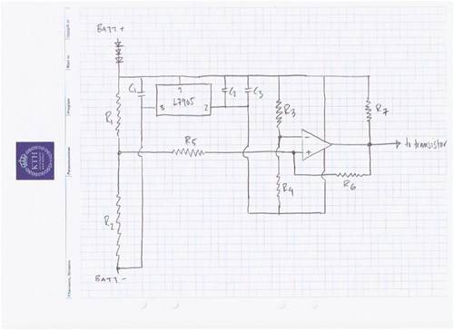
but i have a problem: when i use a negative v.contr. i get a different "ground" in the OP-circuit than the battery ground (-). when the OP-out is low i dont get v=0 but rather like 6v. and i think i need to connect the transistor/mosfet to the battery- pole to get it do work? (it will controll a relay like in Gizmos controller). seems to me my transistor will always be open... anyhow... with r1=8,2k r2=20k r3=33k r4=12k r5=1,2M r6=1,0M r7=3,3k i hope to get OPout high when Ubatt=10,89v cutting the load from the battery bank. then the hystersis sees to it that the load is not connected (OPout gets low) until the Ubatt rises to 12,19v. this is if my calculations are correct of course. is there any way to run the transistor using this setup? i do have a L7805cv that makes things much easier, but they are not quite as common i think? any thoughts? no need to be polite... i know i dont really master this, but you learn by trying, right? /jonathan |
||||
| GWatPE Senior Member Joined: 01/09/2006 Location: AustraliaPosts: 2127 |
Just use an opto coupler to DC isolate the sensing from the control element. Gordon. become more energy aware |
||||
| Downwind Guru Joined: 09/09/2009 Location: AustraliaPosts: 2333 |
Why not intergrate this circuit into Gizmos charge controller and use the same v-reg (7808) That way 1x v-reg will do both circuits. This gets rid of the 7905 and solves the problem as there is no need to have a seperate v-reg for each circuit. What Gordon said will work but it will cost you more than buying a 7805 which as you know will solve the problem too. Just make sure the relay dont disconnect the circuit from the batteries too. 
10.89v would seem a bit to low to me. Pete. Sometimes it just works |
||||
| adonis Regular Member Joined: 13/02/2010 Location: SwedenPosts: 42 |
haha. yes thats a good idea Pete, i never thought of that. but i dont really whant to mess with the other controller, im quite surprized that one works (you dont whant to see inside that box...). Gordon, i have no idea what an opto coupler is, but if you dont easily find it in used up electronics its not really helping... the goal here is all out recycling! i already have a 7805 i found in some computer, but i really would like to use 7905 since it is so common... but maby i will have to go with the 78. well well thanks for your interest. and Pete, i would like to complement you on your guide on making a dump load out of heater element. very nice walkthrough, im gonna make me one of thoose... |
||||
oztules Guru Joined: 26/07/2007 Location: AustraliaPosts: 1686 |
A lot of the earlier high side single switch PC power supplies had opto isolators in them, so should be easy to find. Most CD or DVD players will have them in their supplies as well, set top boxes, satellite reciever boxes etc.. They are very common and almost mandatory for single switch pwm supplies in most consumer goods now. (no one uses transformers any more it seems) A lot (most) pc power supplies have TL494 or ##494 or KA7500 PWM controller chips (they all the same. There are other numbers which escape me at this moment too which are still the same chip). They have two op amps built in, and a 5v regulated output as well..designed as a stable Vref for the op amps to use...... and a PWM output if you want to use that.... so everything you need in one very very easy to find package. Check the data sheets for internal circuits to see what you can exploit. Most PWM chips will have an op-amp or two, and a stable Vref output. ..........oztules Village idiot...or... just another hack out of his depth |
||||
| adonis Regular Member Joined: 13/02/2010 Location: SwedenPosts: 42 |
thats perfect for me it seems! you really understand what kind of input im hoping for here, thanks. now i will have to go through all my junk once again, my wife will love that! |
||||
| adonis Regular Member Joined: 13/02/2010 Location: SwedenPosts: 42 |
i did a quick checkup on the TL494, and i could not spot any OPout pins, they seems to be connected inside? but even if i dont manage to figure that out it is a perfect 5v pos.regulator. and you are right, i think they are very common. thanks. |
||||
| adonis Regular Member Joined: 13/02/2010 Location: SwedenPosts: 42 |
i cant really figure this one out. but you are correcct Oztules, it seems to be everywere! there is a output from the two OP-amps (the outputs are connected, so they can only be used as one). the 5v Vref can give a maximum of 10mA, it is mainly there to drive the chip. but the chip also has two transistors controlled from inside the chip. they have a Imax of 200mA each, its a bit cheap but they can easily be connected in series, so i suppose they can be used to control the relay. if someone figures out how to "disconnect" the PWM-part, and the pulsing, so that the error amplifiers directly controls the transistors, this chip, a few resistors and a relay is all thats needed... i will give you geniouses a few days before i use my 7805. Pete- i was not sure what voltages to use for cut in/ cut out. please advise me on that. i suppose i could post the question on some electronics-forum, know about any good ones? /jonathan |
||||
