
|
|
Forum Index : Other Stuff : 2 projects of interest on the go
| Author | Message | ||||
| VK4AYQ Guru Joined: 02/12/2009 Location: AustraliaPosts: 2539 |
Hi Gizmo I like the concept simple and reliable looking forward to the final drawings, do you have an idea of output yet. All the best Bob Foolin Around |
||||
Downwind Guru Joined: 09/09/2009 Location: AustraliaPosts: 2333 |
Hi Glenn, Mate! i have to give credit for your images of you thoughts, well done 
I often see things in reverse and it would be great with your design not only see how to build it, but how to create the negitive gigs to make the construction easy. Example:- i asked myself how would i setup the axle to weld the lugs on, to mount the stator to, within the right position, square to the shaft. Myself i would make a gig to hold the shaft square to a plane the lugs located into, at the required spacing, prior to welding. Some extra support around the stator mounts to sandwhich the stator between would be an advantage, but im sure you would have a plan there, yet to be shown in detail. I think it is great the backshed is to have a AXFX design for others to work from...good ...bad...or..in different. Its about time!!!! Im just jellous i never got to do it before you, and tell all. (less the great graphics ) I much look forward to the development of this project. Pete. Sometimes it just works |
||||
| vasi Guru Joined: 23/03/2007 Location: RomaniaPosts: 1697 |
I don't have the patience to draw such a project, is a lot of work there. Can't wait to see next stage  ! !
Vasi Hobbit name: Togo Toadfoot of Frogmorton Elvish name: Mablung Miriel Beyound Arduino Lang |
||||
| Gizmo Admin Group Joined: 05/06/2004 Location: AustraliaPosts: 5036 |
Thanks guys. Yeah I've been thinking about the manufacturing side of things, and not 100% happy with the 3 individual stator mounts. I'm leaning towards a flat disc, with a hole in the middle to fit neatly over and then welded to the axle, and 3 holes on a PCD to match the stator. If you are going to get the magnet discs laser/plasma/waterjet cut, then you might as well get the stator mount cut too. The stator mount could be cut from the scrap inside the rear magnet plate, so long as it was 6mm or thicker. 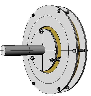
Power wize, I'm going on roughly the same size as Phills axial alternator, so I would images it would be in that power range. Its using 18 50mm * 12mm magnets, 9 per side. Alternator diameter is approx 365mm. Remember this is just proof of concept, to see if its manufacturable from a home workshop point of view. Glenn The best time to plant a tree was twenty years ago, the second best time is right now. JAQ |
||||
Bryan1 Guru Joined: 22/02/2006 Location: AustraliaPosts: 1213 |
G'day Glenn, Yea those 3D images are great and really do show the concept to a Tee. Hopefully soon those 50x15mm N52 neo's will be here and I reckon this design ( or my hybrid version) would fit the bill. I'll be going with a 12/9 ratio for magnets and coils and will be making the first one for 24 volts and the second one for 48 volts. In the spirit of the forum when I get started I'll show every detail of making it so there will another version for people to follow. Cheers Bryan |
||||
| Gizmo Admin Group Joined: 05/06/2004 Location: AustraliaPosts: 5036 |
12/9 is a good combination. I'm going to start with a 8/6 for the prototype, that way if it flops I've not wasted too much money. You could pretty much use any 4/3 combination for magnets and coils, I'm using the info over at Hughs site and Other Power as a guidline for coils and turns etc. Electrically and magnetically its the same as their alternators, just built differently. This weekend I'll do up the cad files and get them off to the waterjet next week. Glenn The best time to plant a tree was twenty years ago, the second best time is right now. JAQ |
||||
oztules Guru Joined: 26/07/2007 Location: AustraliaPosts: 1686 |
Nice design Gizmo. I would go with the 12 magnets, as you will have a lot of dead space with only 8 on that plate..... or very very big magnets.... or poor performance. The stator: Have you considered molding a steel center plate into the stator itself. You can go out to nearly the inner radius of the coils without causing much if any eddy currents in the plate. This could be them bolted to your "flange" you are talking about being welded to the shaft. Flexing of the stator concerns me holding it too close in the inner areas. The usual design holds it from the outside (plenty of leverage.... and I use 9 holding points), but if I were to hold it from the inner radius area, I would want as much purchase and stiffness as possible..... or bolt the glass stator directly to the flange (big as possible). Look forward to the final iteration. With something around the two disks, weather protection is a welcome possibility. ...............oztules Village idiot...or... just another hack out of his depth |
||||
| VK4AYQ Guru Joined: 02/12/2009 Location: AustraliaPosts: 2539 |
Hi Gizmo Peter and I where having a talk on the dog and bone about the stator last night as I didn't know how you where setting up the coils, he said they are set in epoxy and my suggestion for what its worth was to set the coils in apiece of plywood with the holes cut in it to hold the coils and it would allow a hole through the center of the coil to assist cooling, this would allow a more stable base stator and it would be easier to wind coils on a former to fit in the hole and then encapsulate the ply in epoxy using a vacuum bag method to fill voids, a small tube could be used to provide the center hole and also be the base for the winding bobbin to make it neat and quick to wind. Also a lot less epoxy to use for the stator with no distortion from curing heat and other factors. Just a suggestion, if you arn't going that way already in your design. All the best Bob Foolin Around |
||||
| oztules Guru Joined: 26/07/2007 Location: AustraliaPosts: 1686 |
Bob, Epoxy has been found to be good for the magnet plates, but not the stator. Fiberglass and resin has been found to be more suited for this part. The ply system you talked of has been tried before, but has not become mainstream....I don't know exactly why, but has been largely ignored..... maybe the resin stator is just too easy to get right from the get go. It does not warp on curing (because of the mold design), and is incredibly strong. It is not worth sacrificing any strength for cooling with these machines (holes). They are essentially resistance loss devices, and providing the furling point is sensibly selected (mine can do 5kw, but now furls at about 1-1.5kw) all is fine. The wind is unforgiving, and if you push the envelope just a bit to allow for a marginally better cooling system, it will burn up for sure in the next gale. If you set the furl properly, any minor gain from cooling technique (holes or thermally conductive filler etc) will make no difference. If the furling is poor, it will burn up regardless. 10-15% makes no difference when things are going poorly (hundereds of percent.... these things just keep developing more and more power as you spin them faster) An example of this was a recent testing I did with new furling. I wanted it to furl at 20 amps, but messed up, and a gust took it to over 60 amps (57v???). A gale would have vaporised it 
My first stator was a technical disaster (far too much hardener.... set in 5 mins with smoke to boot.... but still works perfectly. (the one that did >5kw). It is a well trodden route now. A full resin /glass stator has been found to be the best as yet. I know Bob with the beautiful 20 footer with the MPPT, used an odd technique incorporating holes... but I believe he has had stator problems fairly recently.... so it didn't seem to help either. I can only suggest to Gizmo.... tried and true for the first one..... and get sexy after that. If he builds this one right, his previous 400W F&P will be but a distant memory...... and then he can build as many stators as he wants  (with a mold this is quick and simple too) (with a mold this is quick and simple too)
............oztules Village idiot...or... just another hack out of his depth |
||||
| VK4AYQ Guru Joined: 02/12/2009 Location: AustraliaPosts: 2539 |
Hi Oz Point taken on the resin stator, what I was trying to do was make the ply a composite foundation for the stator. As I have not tried to build one yet I bow to your experience. Would a current limiter in the line be a way to go as it would limit the current to a safe level once that was reached. What I am trying to do is to get away from furling altogether as the gyroscopic forces and aerodynamic loading changes causes damage to the machine also. My thing at the moment is to make a strong enough turbine to withstand 80 ms, normal aircraft propellers do this all the time. Where I live the average wind is low but when it decides to blow 30 to 40 ms is possible. All the best Bob Foolin Around |
||||
| Downwind Guru Joined: 09/09/2009 Location: AustraliaPosts: 2333 |
Its funny how different points of view can arise from a discussion. My take on the discussion with Bob, on using a piece of plywood was ..1 to add a little strength to the resin casting as resin has no strength without glass mat added to it, and ...2 to act a a coil alignment guide that could be casted into the stator. I do think only a fool would cast a stator without a few layers of glass in it for strength. There has been some disscussions on stators deforming with internal heat and poor mounting alignments. Well nothing can help poor construction but a sheet of plywood would add a lot of ridgid strength to a stator and is easy to make. Point 2B... as Oz pointed out and Gordon has said many times too, with a well furled mill these problems are non exsisting. Pete. Sometimes it just works |
||||
| VK4AYQ Guru Joined: 02/12/2009 Location: AustraliaPosts: 2539 |
Hi Pete I don't like furling is the trouble, a prop buzzing around within its design limits pleases me more. My introduction to wind turbines 40 years ago was rebuilding the damage primarily caused by furling accidents so I suppose I am biased. I haven't seen a single design that incorporates a hydraulic furl damper to slow the furling and lesson the forces generated by wind flow and gyroscopics. I have watched the furling on my little mill and the strain it puts on the pole and generator are quite pronounced. I have now locked the furling and fitted blades rated to 2000 rpm for a test. All the best Bob Foolin Around |
||||
| Downwind Guru Joined: 09/09/2009 Location: AustraliaPosts: 2333 |
I have seen some badly furled mills that hunt as i would call it with big gyroscopic forces applied by their actions. I visited Gordon on a windy day and watched his mills react to the wind and furl accordingly. They floated on the degree of furl according to the wind speed, no harsh gyro movements, just a pleasure to watch. Not once did i feel it even got close to not being in total control. Also whisper quite that you hardly knew they were directly above you. This is all a credit to his craftmanship of the mills. There is a lot more to a tail design than hanging a road sign off a chunk of pipe. Its more of desiging a saftey device rather than a directional device as is often the case. Pete. Sometimes it just works |
||||
| oztules Guru Joined: 26/07/2007 Location: AustraliaPosts: 1686 |
Hmmm..... Well the world is a different place since the advent of Neo magnets. Before these things turned up, the world had all the problems and advantages of the F&P. In fact the F&P is one of the better non-neo designs out there. It is able to capture the low winds fairly well. The AWP is another example of non-neo designs. They all share one thing in common..... they don't stall limit very well, and are more likely to use the blades better power band in 10 mph-20 mph winds.... because it is near impossible to stall them, they are more likely to run nearer their best TSR. An AXFX can kill the blades performance if not matched properly.... too electrically stiff. Matching a good AXFX alternator to the load is far more pikky than for the iron core units (very soft comparatively) The other thing they share is reactance limiting. Here you can fix the furling, and let it spin it's heart out if the blades and neighbors can handle it, and the alternator could care less. You can run it at 2000 rpm, and it will behave the same as say 600 rpm. With air core neo designs (like mine etc), this does not happen. They are so good at low rpm power outputs, you can easily stall them at 100 rpm if you wish. They are good for picking up winds of 6mph and converting it to power, but...... there in lies the problem. Being the greedy beings we are, we want it all. We can design it to be a low wind performer, but then when 15-20 mph winds turn up, it will try to stall limit. It will probably do this pretty well too, but when the real wind turns up, it goes the other way. It will break stall sometime if the furling is not correct, and when this happens, the difference is stark with the iron core machines. Iron cores will current limit, and thats it.... it is up to the blades to hold together as it speeds up to destructive speeds (balance will be vital here). The air core will simply start to develop huge power, and bend the current meter over the end. The Esq R losses in the stator will at some point cause the stator to cook. The blades will not speed up like the iron core, as the power required to drive the genny will go up in a squared or more fashion, and so over revving like the F&P is not common. I doubt mine has ever gone over 500 rpm .... except when experimenting with resistance loading) To get around this, it is best to design for absolute minimum resistance stators.... more magnet less copper..... even better- design for very late cut in, and have a boost converter take care of the piffle winds Then the stator phase resistance will be in the fraction of an ohm range. (Note for Gizmo: don't skimp on magnets... it will end in tears as your stator will by necessity be high in resistance. 8 magnets is not likely to be enough for an alternator with your size disks.... unless you furl early, and have little blades..... and don't use the 1"x 1/2"X 2" cheap mags that Hugh and Dan used to use. (These end up with burnt stators for anything larger than 8 footers) think resistance resistance resistance.) This gets the stator losses down quickly, and if stall is a problem, resistance can be added --outside-- of the stator (line loss is good here). So a furless axfx is not an option. No point in having high speed blades, the stator won't survive it.... nor the batteries if it is in the 4m range. So in answer to your question Bob..... No current limiters will only allow the mill to unload, and rpm to rise to dangerous levels. We see this with the F&P units now (self limiting). With AXFX (built decently), we can simply load it up before it gets too bad, and stop it, or stall limit it. Stop it is best, as by now (storm on the way), the batts will probably be be boiling anyway We can artificially load it up beyond battery loading, and stall the blades some, and shed the windpower. This works for AXFX as it has the electrical stiffness to do it. The F&P style will simply do more amp turns (not necessarily watts either) and current limit.... and run away as usual (without furling).
The best of all worlds with AXFX will be variable pitch, no furling. This is a killer combination, as all the best traits of the low speed AXFX can be exploited, and have safe operating speed as well.... I will do this one day, as it is by far the best setup. Like you, I cringe at furling, but it is still the best option to save the mill in almost any speed winds. I have a love hate relationship with it...... but I still stop the mills in bad weather. Mine are too close to the ground, and so suffer from excessive buffeting they would otherwise not be subject too 15m higher up. Pete, Stators should have as much glass as is humanly possible to squeeze into them. It is not until you have a slab of glass/resin/copper 19mm thick and 20 inches in diameter, that you realize how stiff this stuff can be. It is truly tuff. Ply is sooky by comparison. 20mm ply I can bend slightly (and that is before I fill it with large holes for the coils), my stators I cant. It feels and acts like rock..... Flex is the enemy. Huge forces are at work in the stator gaps on the bigger AXFX machines, and wobble is not desirable at all. Ply while full of glue etc, has still a lot of wood fibre unaffected by it, (can still compress the ply with a nut/bolt) and is comparatively soft compared to a glass composite. ..........oztules Village idiot...or... just another hack out of his depth |
||||
| Gizmo Admin Group Joined: 05/06/2004 Location: AustraliaPosts: 5036 |
Yeah I agree a 12 magnet 9 coil arrangment is better. I've spent the last few days in CAD trying different layouts, moving coils and magnets around, and the 12/9 or higher magnet/coil count works very well, which is why just about every axial flux out there is using a 12/9 configuration, its the logical choice. However I'm going to use a 8/6 for this first build. Its a challenge, but I want to see if it can be done with no wasted space between the coils. The overall diameter is unchanged from a 12/9, so I'll be able to reuse the waterjet cut plates when I upgrade to a 12/9 later. To better make use of the lower coil count, I'm winding wider diameter coils to fill the space between coils. This means more wire, and more resistance, so to counteract that loss I'm going for a flatter stator between the magnets, 10mm, which will reduce the wire length. This also means closer magnets, and more flux intensity, so I'll gain some power there. The stator will be cast with a step, 10mm thick where the magnets pass over the coils, and 15mm thick where the support bolts go through and the outside diameter.. Where the bolts go through the stator there are two steel reinforcing plates, on either side. I'm using 3 12mm bolts to postiion the stator. The bolts will only be short, there is 25mm between the stator and the mounting plate welded to the axle. 3 Bolts means easy adjustment, but 6 should probably be used for a 12/9 or bigger. This pic shows the stator and its reinforcing plates. Between each 12mm bolt hole there are smaller 8mm bolts to help clamp the sandwitch together. I think this should be strong enough, but time will tell. This area is where all the big forces are, especially if the mill is shut down in high winds. I can cast this part of the stator thicker if needed, making it stronger and closer to the stator mounting plate. 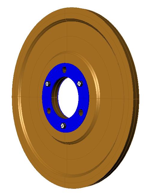
Glenn The best time to plant a tree was twenty years ago, the second best time is right now. JAQ |
||||
| GWatPE Senior Member Joined: 01/09/2006 Location: AustraliaPosts: 2127 |
Sorry Gizmo, if this a bit off topic. Hi Bob, but Soma, and Whisper have hysraulic dampers on some of their windmills. The dampers are usually the first component to fail. The gyroscopic forces don't show up as a problem on a machine and tower that is built with strength in the right places. I suppose problems will develop wherever shortcuts are taken in a design, and components don't have sufficient strenth for the job. Gordon. become more energy aware |
||||
| Gizmo Admin Group Joined: 05/06/2004 Location: AustraliaPosts: 5036 |
Regarding the stator material, yes I planned on using fibreglass resin, with as much glass as I could get in there. I do agree the coils need to be thoroughly soaked through with resin. I belive, and this is just my opinion, that one reason for the failures in these stators, apart from furling too late, it the individual turns are not properly secured within the coil. As the magnets pass over a loaded coil, the individual wires are been forced against eachother, as they try to squeese out of the flux path. In my view this means the wires, given the chance, will be moving around inside the coil, and in the process rubbing off their insulation, causing internal shorts. Eventually this leads to a overheating coil, the problem escalates until you get a coil failure. The fact we see failed stators with only one or two very burnt coils, while the rest of the stator apears to be OK, confirms this in my opinion. If the stator was overloaded, then you would expect to see all coils burnt. Impregnating the coils with resin locks them together, they cant move against eachother. Either applying resin while you wind the coil, or vacuum bagging the finished coil is a must do I think. Glenn The best time to plant a tree was twenty years ago, the second best time is right now. JAQ |
||||
| VK4AYQ Guru Joined: 02/12/2009 Location: AustraliaPosts: 2539 |
Hi Gordon Point taken on the furl dampers but you also noted that if everything was built with enough strength to absorb the forces then no problems, this applies to the furl dampers as well and maybe they haven't made them strong enough, or designed them properly, to me it demonstrates the forces being absorbed by structure and bearings. I may be stupid for doing so but I am going to persist with my non furling program for the moment. If I go ahead with a furling machine on glenns new design I will make a damper as the mill I have has a furling tail and after watching it slam around I have licked it up. All the best Bob Foolin Around |
||||
| VK4AYQ Guru Joined: 02/12/2009 Location: AustraliaPosts: 2539 |
Hi Oz Thanks for the explanation on the AFX machine I have never worked on or built one so am in the dark a bit, however it sounds like a match made in heaven for the VAWT I am making as its revs don't run away like a HAWT in high wind it is a high torque not high speed mill the output shaft is 450 rpm maximum so a 3 foot diameter rotor would be a peach, the only thing that concerns me is the cost of the magnets, you mentioned the substandard magnets used in some machines what is the problem with them so I don't buy the wrong ones, and what gauge wire would you suggest, as I have some 16 gauge wire I used on coils years ago and would like to use it if possible, also I used to wind to 5 turns per volt for iron core is that still valid in this design using air core. On the plywood discussion, a sheet of ply vacuum bagged and resin impregnated is four times stiffer than a untreated sheet, I have used this method in aircraft construction and is extremely strong for high stress locations, I know that resin glass composite is very hard and rigid but this gives a high point stress on the mounting system and is prone to inter granular stress in the resin. Glenn I would like to thank you for providing a solution to my VAWT generator problem by your project. It has made me look in a new direction that is more practical for a slow speed machine. All the best Bob Foolin Around |
||||
| oztules Guru Joined: 26/07/2007 Location: AustraliaPosts: 1686 |
Sorry Bob, I didn't see this till now. (busy fixing other things for other people). The magnets I referred to were used in a lot of earlier designs by Hugh Piggott and DanB at fieldlines. Both have printed books that clearly and concicely describe the manufacture in fine detail. The problem stems with the choice of magnets for 10' machines. The 1"x 1/2" x 2" magnet size used extensively some years ago, led to stators of higher resistance than would be useful for a 10' machine in good winds. To make matters worse, because you need to get the turns/volt sorted out with a test coil, it is easy stuff for readers/constructors to "roll their own". This usually entails deciding on your cut in speed, working/guessing your TSR, and calculating the rpm that cutin may happen..... they then get just a little greedy, and decide to catch the winds down even lower..... so they don't see the mill turn and not put something into the batteries. This means more turns.... weakish magnets means even more turns... and very soon we are driving phase resistances near 2R. Now this is a recipie for cooked stator if the furling is not right. Bigger magnets (2" x 1/2" rounds) seem to push the burn out thing completely out of the picture. I have not heard of a 10' machine burning up with these magnets. They will usually have well below 1R phase resistance, which as you can appreciate really lowers the loss in the stator. So it was not that the magnets were bad or substandard, just that they were not useful for over 8' machines, because they would always give high resistance stators (comparatively) The other quirk, is that they were less inclined to give you any real stall limiting, and so were more likely to let the blades run at their optimum, which sounds good, unless you cant handle the power. So they actually make more power in medium winds generally than the bigger magnet machine, but are more prone to heart break.... when the real winds turn up, big magnets are way cool. For your 5 turns/volt. I assume that is for transformer winding on decent cores ( I seem to recall 6sq ins @ 50hz is near 1 t/v ) No it has no relevance with these coils. These coils are air coils, with very little reactance properties. The air gap itself helps keep the reactance problem away, as the airgap is huge compared to the gap experienced by iron core machines, so the back MMF has a real job on it's hands trying to influence the Neo fields very easily...... so they don't run away in a big wind. They can be calculated reasonably as resistance machines. This will leave ideal at the higher power ranges. as back MMF must start to kick in somewhere... but I haven't witnessed it yet. Here the turns is dictated by the gap, and the flux, the angular speed that the magnets cut the coils (frequency. or degrees/second, not peripheral inch/second). A simple test coils gives you the turns/volt at your chosen RPM. Then we get the single coil AC rms reading from our cheap DVM, multiply by the number of coils in the phase (usually 3 for a 9 coil design). That gives us our phase voltage. Usually we run star, so we can multiply that by 1.7 to get star AC voltage, and then multiply that by 1.4 to get the peak DC that will start charging the battery at cut in. So if we had a 100 turn coil being tested at cut in rpm, and saw 7v, we multiply 7 X 3 for the phase AC voltage, X 1.7 for star AC voltage = 35.7 and X 1.4 for the DC = 50v. This will do for cut in for a 48v system. Next thing, is to design your coils with as much copper as the winding space will allow. So 1/9th of you real estate at the coils diameter is how big your outer for the coil will be, and the inner will be a fraction less than the magnet diameter. (Yes efficiency is lost below magnet size via cancellation to some extent, but the extra volts generated with this shorter less resistance wire is a win.... so we take it) Then chose however much of your available wire will fit in in how many turns in hand . 16# is fine, but you will probably need a few inhand to get the window full, and keep the R down to minimum. Individual wire size is immaterial, it will be the effective gauge or circular mills if you like (so many in hand... ie 2x16G = 1x13G ...or #16 = 2581 cmils, and #13=5180 cmils etc, mixing gauges is fine also , and may help packing ratio a bit  . .
Now the above is general for disks that have the magnet spacing at around the half a diameter of the magnet separating the magnets. If the gap is much much larger than this (big disk perhaps), then it may be more useful to use more magnets, and coils in a (4 mags:3 coil ratio for 3 phase). For a vawt, you may want to go with larger disks, and 16 magnets to 12 coils etc. Any cut in can be achieved with these things. Sky is the limit I suppose. Remember, at the power you have designated for your design we want efficiency to be at least 50 or more pecent (eg. @ 3000W we want to see less than 1500 watts lost in the stator, and more than 1500watts into the batteries). This isn't as bad as it first seems for the design. An iron core will not get there to waste it in the first place (back MMF reactance problems way before then), the AXFX will/can. It is true that the larger the stator, the better the natural cooling. Sadly, unless you pull one out of the barrel, the vawt will not trouble the alternator unduly. They seem to be always well lower on power than the designer expects..... maybe you can change that So if it can turn the shaft, you can easily make an AXFX to match it...I expect most of the time you will be less then 200W. 
The stator losses are a squared function, so most of the time efficiency will be very high. It will be only when you don't really want any more power that it will be in the lower end of the efficiency range..... ie near the limit to what you can usefully put into the batteries.... big winds A Vawt will probably not drop below 85% I suspect.... unless it is a very small AXFX
Stator: There have been many mavericks doing their own thing, but they always come back to the old glass stator. It is the strongest, and easiest one to make with the least work. It is just the best so far... (Fibreglass resin, H/temp epoxy(not normal stuff) etc)... but go for it...... but I would not bother with anything else. Whatever you get up to, the stator must be true and flat and strong as hell. ...............oztules Village idiot...or... just another hack out of his depth |
||||
