
|
|
Forum Index : Solar : Serious Solar
| Author | Message | ||||
| RossW Guru Joined: 25/02/2006 Location: AustraliaPosts: 495 |
Errr... that was quite litterally just somewhere to start the ball rolling. It's nothing even like a comprehensive start. I hope there can be some discussion about the value (or otherwise) of using examples to explain to people not familiar with things (electricity, for example) what "stuff" is. Over my (many) years of teaching people stuff, I've found that making them learn parrot-fashion works for things like the times-tables and morse code, but for most everything else, understanding HOW or WHY things are is far superior. So putting concepts like watt-hours in terms of a working day, and the harder you work or the longer you work the more you get done may help some people grasp the difference. |
||||
| Chris220220 Newbie Joined: 17/02/2010 Location: AustraliaPosts: 29 |
This sound like my Apprentice Technician Electronics training. Now that is a few years ago now. The water analogy work pretty well. Thats how I try to explain battery life. 50Amp/hr 12v battery is 50 amps for 1 hr or 1amp for 50hrs (if perfect but we don't want to flatten it). No Dad that 50 Amp/hr battery won't run your 2-3 amp fridge for the Easter holidays with only the 10watt solar panel to recharge it. Maybe the old VIR, PWV triangles would help as well. Cover the one you want to calculate. ie. Power(P) = Volts(V) x Amps(I). Amps = Power/Volts 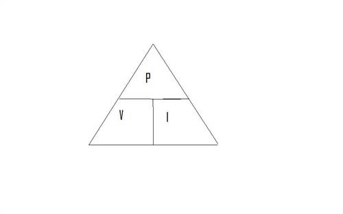
Regards Chris |
||||
| VK4AYQ Guru Joined: 02/12/2009 Location: AustraliaPosts: 2539 |
Hi Ross I have added a bit and now send for your correction / critique I tried to include the wire resistance table but the format was lost any suggestions? I don't know how the format works on the forum. Hi Chris Thanks for the contribution to the discussion and hopefully a terms definition All the best Bob Terms and Definitions Electrical. Volts. Voltage is a measure of the "pressure" of electrical energy, in the same way that water pressure is measured. The basic unit is the Volt. Also referred to as �EMF� {Electromotive force} Larger voltages are expressed in kilo-volts (KV) and mega-volts (MV), while smaller voltages are expressed in milli-volts (mV) and micro-volts (uV). 1000uV = 1mV. 1000mV = 1V. 1000V = 1KV. 1000KV = 1MV. Nominal voltages. A 12 volt battery in a 12 volt system. A 24 volt battery in a 24 volt system A 48 volt battery in a 48 volt system These are nominal voltages as the actual measured voltage of the batteries vary to reflect the state of charge of the battery. Charging voltages. Charging volts are higher than system voltage to cause current to flow into the battery from the charging device. Like water running down hill into a pond, the hill must be higher than the pond to allow the flow of water to the pond. Amps. Amperage is a measure of the "flow" of electrical energy, in the same way that water flow is measured. The basic unit is the Ampere or abbreviated to Amp and is like the number of buckets of water flowing in the stream of water. An Amp is defined as an electron flow of 1 coulomb per second, and one coulomb is defined as a flow of : 6 million , million , million electrons. Smaller currents usually expressed in milli-amps (mA) or micro-amps (uA), larger values in kilo-amps (KA). Watts. Watts are a measure of Power/ Energy, the amount of work done by the electron flow. Watts are used in various fields, the term and the power are the same, but not necessarily immediately obviously so. Eg, a gas burner may be rated in watts or kilowatts. A 1000 watt gas burner will heat a room just as much as a 1000 watt electrical heater because they both produce the same amount of work, power. From a electrical perspective, it is a heater on a 250 volt power source drawing 4 amps In electrical terms, watts are generally the Volts times the Amps. V x A = Watts A 12 Volt battery delivering 10 Amps is supplying 12*10 = 120 Watts. Watts are an instantaneous measure - that is, there is no time. A watt is a watt, for as long as you consume or produce it for a period of 1 second. In AC circuits, Watts of actual work may be much less than Volts*Amps. See: Power Factor. VA. Volt-Amps are similar to Watts. VA is usually only used in AC circuits hence the term used to rate AC power generators as so many KVA. It is used primarily in devices that have a Power Factor of less than unity. 1 to 1 Watt Hours. Watt-Hours, and their more common big-brother Kilo Watt-Hours or KWh are the most common way of expressing electrical WORK DONE. One watt being made or used constantly for one hour is one watt-hour. Remember, this is a measure of WORK DONE. If you go to work for a day, but spend 4 hours of it drinking coffee and reading the paper and the other 4 hours actually working, you have really done a half-a-day work. Same with watts. If you use one watt for half an hour, and nothing for the other half hour, you have only done a half-watt-hour of work. If you do nothing for half a day and work twice as hard for the other half, you've still only done one days work. So taking no power for half an hour and two watts for the other half hour is 1 watt-hour of work done. Smaller amounts of power are sometimes measured in watt-seconds Power Factor. Power-factor is a moderately complex concept. In real AC circuits, a combination of resistance, inductance and capacitance exist. Inductance and capacitance have the effect of moving the current out of phase to the voltage resulting in less work being done than if current and voltage were perfectly in phase. Think of it like pushing a car. If you push it from directly behind, it's no to bad. If you push it sideways, you're exerting a lot of effort but the car isn't going anywhere. In between these two, sees you push the car diagonally - some of your effort goes into moving the car forwards while the rest is just wasted effort. Power factor is the measure of how "efficiently" your effort is being applied. It ranges from 0 (pushing directly sideways, with no useful work being done) to 1 (pushing directly in line, all the effort being useful work). Power factor at Play Watts, in an AC circuit, is Volts * Amps in the case of a non inductive load power factor of 1. Watts in a AC circuit with a reactive load like an electric motor is Amps x volts power absorbed, and the amount of work done is less due to the power factor. Eg: 5 amps x 250 Volts =1250 watts x PF .8 = 1000 watts of actual work done, a loss of energy of 20% This loss is represented by the amount of heat generated by the motor. NOTE This definition ignores the effect of resistive loss in the circuit. Resistance. The Resistance in a circuit carrying DC current is the Resistance to the flow of electrons in the circuit, this is caused by several factors, the primary one is the Resistance of the conductor carrying the electrons, the resistive property of the conductor metals and the cross section of the conductor. Commonly used conductors. Factor Silver 1.6 x 10 to the 6th Copper 1.7 x 10 to the 6th Aluminum 3 x 10 to the 6th Brass 7 x 10 to the sixth Iron 12 x 10 to the sixth As a conductor Silver is the best but very expensive, Copper is the best compromise for general electrical use as in our projects. The lower the Factor the better the conductor. The Table below is from Glenn's information section I would recommend you read the Section in Information on Page 1. Common copper wire sizes and resistance AWG Max I * Inch Dia mm Dia per 1000' ** per km ** 22 0.918 0.025 0.644 16.46 54 20 1.46 0.032 0.812 10.35 33.95 18 2.32 0.04 1.024 6.51 21.36 16 3.69 0.05 1.291 4.09 13.42 14 5.87 0.064 1.628 2.57 8.43 12 9.33 0.08 2.053 1.62 5.31 10 14.8 0.101 2.588 1.02 3.34 8 23.6 0.128 3.264 0.64 2.1 6 37.5 0.162 4.115 0.4 1.31 4 59.6 0.204 5.189 0.25 0.83 2 94.8 0.257 6.544 0.16 0.52 1 119 0.289 7.348 0.12 0.39 * max safe current in a tightly wound coil ** at 25 degrees C Source: The Radio Armatures Handbook 1978 From the above table we can accurately calculate the losses in our DC wiring running long distances from the power source to the load. Remember that we have 6 million , million , million little electrons scampering through the conductor for every amp we are using, so the larger the conductor the better the flow of electrons, like a larger pipe will carry more water for a given pressure. Other causes of loss by resistance in the circuit is contact resistance caused imperfect point contact at the termination of the conductor. We all have had a car not starting by a dirty battery terminal, { Contact resistance } clean it and away we go. Also caused by crimp terminals where some oxide on the crimped wires causes some of the strands of the conductor to have less than perfect contact within the crimp. { Solder all terminals for the best conduction of current} Also the inclusion of shunts for measuring current flow cause a small loss. All these losses are reflected by heating in the conductor, so a sensitive thermo probe can find warm spots in the circuit to find bad terminations. Resistance in AC Circuits In AC circuits we have ALL THE ABOVE plus Inductive Reactive and Capacitive Losses Inductive losses are caused by the establishment and collapse of electromagnetic fields in the circuit on every cycle of the AC current, as when there is current flow in a conductor, a small electromagnetic field is induced around the conductor, and that requires some energy, most of that energy is recovered as the field collapses, but not all, then a field of the opposite polarity is induced and subsequently collapses on each cycle of the alternating current Small Losses but they are there. We could liken this to sitting in our car on a level surface and rocking between forward and reverse in the auto gearbox, very soon the gearbox will heat up by the energy dissipated within it. The Capacitive Losses are caused by the energy used to establish a charge in the capacitive elements of the circuit,as where the conductors are running paralleled with an insulator between them and also fixed objects with a dielectric between them and the conductor, This capacitive charge and discharge and recharge are present on every cycle of AC. These two effects in combination cause losses in AC power due to what I call a leaky hose effect, much like the water hose with a lot of little holes in the side used to water our gardens, if we have enough water that is. The combination of these effects in an electric motor are the cause of a less than unity power factor and the resultant losses. They are present in all conductors carrying AC power, and can be realized and demonstrated by the heat buildup in a coiled power lead, the wasted energy in a coiled lead can cause it to burn if high current id being drawn. Foolin Around |
||||
MacGyver Guru Joined: 12/05/2009 Location: United StatesPosts: 1329 |
Bob et al All this stuff is good. I'm learning all the time, but I think I should interject something right about here. As 'background' information, I am a former ICBO building inspector and as such was a county "Electrical Inspector" for a couple of years. That being said, I still consider myself a "techno-dummy" when it comes to electricity. I find it very useful to go back every now and then and re-read the basics, so I don't make a giant boo-boo when it comes to electricity. In that regard, I think posting all the basic stuff here on the 4m is important and I think a special "tab" or "link" to a page all about electricity, it's manufacture and use would be beneficial to all. I think if such a page is posted, it should be tailored to the "wind" and "solar" side of things so folks don't have to "interpret" their answers based on theory. I think solar applications and wind applications should be presented as solo topics and maybe at the end of each section another story linking the similarities of each to each other might be appropriate. If "plumbing" were a topic for discussion here, I'd gladly volunteer my time and expertise to writing a tutorial, but sadly, plumbing is not part of this gig.  For those who don't know already, I've been a plumber for 46 years.; started with my dad when I was 15. For those who don't know already, I've been a plumber for 46 years.; started with my dad when I was 15.
Well, that's my input. Please keep it coming. Like I said, I'm learning bunches; thanks to all! Edit: Link for Bob. I find this Link very helpful. . . . . . Mac Nothing difficult is ever easy! Perhaps better stated in the words of Morgan Freeman, "Where there is no struggle, there is no progress!" Copeville, Texas |
||||
| VK4AYQ Guru Joined: 02/12/2009 Location: AustraliaPosts: 2539 |
Hi Mack Thanks for your comments, and I must apologize for diverting the thread you initiated to some extent, Ross and I had a bit of banter on my loose use of terms when posting as if everyone would naturally understand what I was talking about,I'm afraid after a while we get tied to our jargon and expect everyone to understand the terms and definitions we are using, I'm sure you as a plumber can relate to that with the many terms you would use as a working plumber and trying to communicate them to a DIY or newbie in the trade, so what we are trying to do is put a definitions article together for the outline and definition of these terms and important related factors. We would appreciate your input on how we are going with the definitions to make it understandable, as with your electrical experience you will be a good sounding board for the development of the subject. I did try to put a wire table in the text but it lost format I don't know why, also thanks for the link it is very informative and I think it should be included in the Appendix of the text. All the best Bob Foolin Around |
||||
| RossW Guru Joined: 25/02/2006 Location: AustraliaPosts: 495 |
OK. Please don't take offence. There's a couple of things here I'll add my views on - it'll be up to Gizmo I guess, to make the final call on... Not sure that references to EMF add anything. Perhaps a seperate entry for EMF saying simply "See 'Volts'" ? I'm uncertain here. "Typical" perhaps rather than "Nominal". Do you include references to 1.5V dry cells? 1.2V NiCad/NiMH etc? 3V for lithium? 240V AC for domestic power in .au? 110/120 for other parts of the world? 17.5V or so for '12V' PV modules? Where do we stop? I think the reference to buckets here is bad, as it implies disparate chunks and makes me at least (and others?) ask "in how long?". It's a continuous flow, and I think that is what needs to be emphasises. Is this really necessary? Does *ANYONE* give a rats? Especially a n00b? Perhaps a link to a more detailed resource for the scientific terms if anyone really wants it. I doubt many people reading this will have any concept of just how small an electron is! I'd be happier if that sentance spelled out the power, rather than being a stand-alone sentance in itself, which could easily be misread out of context. "From a electrical perspective, a 250 volt heater drawing 4 amps would take 1000 watts." for example. NO! NO! NO!!! A watt is a watt is a watt. A watt for 1 nanosecond is a watt. A watt for a million years is still a watt. A watt has no reference to time in any way, shape or form. Lets not complicate the situation with if's and but's. In an AC circuit, watts is ALWAYS Volts * Amps * Powerfactor. If it's a purely resistive load, powerfactor is unity, so Volts*Amps*1 is still true, and is not a complex calcuation :) It's also one less formulae or condition to have to remember. I disagree here. Amps * Volts * Power "Absorbed"?? The power isn't "absorbed", it's merely converted to another form - generally heat. In a purely mathatical sense, if you have a 240V * 10A and powerfactor of 0.5, you're "wasting" half the power, or 1200 watts. 240 * 10 * 1200 ??? I don't think so! But wait, this gets a LOT more complicated - and much more complicated than I think needs to be explained in such a basic "terms and definitions" section. If you have reactive load, the reactive component is actually "wattless". That is, the (purely) reactive part will be 90 (electrical) degrees out of phase and consume ZERO watts. What really happens is that the RESISTANCE in your cabling (or in your example, the motor windings) has to pass the full CURRENT, not just that portion doing work. So a 240V/10A (2400VA) motor at PF of 0.5 will do 1200 WATTS of work, but take 10 AMPS of current. The windings (lets just say 3 ohms), will have to pass that entire 10 amps of current so the I^2R losses are 10^2 * 3 = 300 *WATTS*. That is where the heat is comming from. But 2400 VA less 300 watts of HEAT, less 1200 watts of WORK still leaves us 900 VA unaccounted for. The simple answer is, we're not actually USING 2400 WATTS. You see why I wanted to skirt around this one? :) PowerFactor isn't really just an expression of efficiency (ok, my bad, I implied that in my original post, but it really is a lot more complex than that). But it can't because resistance is the primary reason low powerfactors are a problem. A fluro tube has a very low powerfactor, but they are not inefficient. It's the effect of all those wattless amps being drawn over the cables that pose the problem. 1.6 x 10^6 *WHAT*? 1.6 million "somethings" is almost completely meaningless. PROPERLY crimped terminals/lugs never suffer this problem, because when done properly the wire actually welds to the lug and makes a permanent, low-resistance connection. If you said "Badly crimped" fair enough. As for soldered - I dispute that. For high current connections, solder has a significantly higher resistance than a properly crimped connector, and WILL get hot. Soldering also creates a failure point outside the connector where flexing cables tend to fail. It's actually on every HALF cycle. The heating in the cable isn't due to the inductive OR capacitive losses. As I said above, purely reactive power is wattless. The heating is the old "I-squared-R" losses. Passing the same *DC* current through the same cable will result in the same heating. |
||||
| Barry T Coles Senior Member Joined: 30/07/2009 Location: AustraliaPosts: 109 |
|
||||
| RossW Guru Joined: 25/02/2006 Location: AustraliaPosts: 495 |
Thanks Barry, you make EXACTLY my point. A unit gets MISused or MISquoted and it becomes gospel for someone else. Flow of a stream, or pipe, in the terms you use, is measured in volume/time. Amps are not "over time". Amps (and volts) are instanteneous, in the same way water *PRESSURE* is. The analogy of water "flow" to amps was to give a tangable reference. A big, wide river is obviously a "lot more flow" than a small stream.... while certainly, if you want to quantify how much water is flowing, you do need to include a time component. I wonder if there is a natural unit quite like "amps" we could use in lieu of the water flow example. One that doesn't have a volume/time relationship! |
||||
| Barry T Coles Senior Member Joined: 30/07/2009 Location: AustraliaPosts: 109 |
Ross I think water flow is probably the best we could use;everyone knows what it is and can relate to it, it's the clarity & simplicity of explaination to the uninformed that really counts. Lets take Chris's example and assume that there is only the battery & no recharge. No Dad that 50 Amp/hr battery won't run your 2-3 amp fridge for the Easter holidays with only the 10watt solar panel to recharge it. If Dad couldnt grasp the situation of a 50 Amp/hr battery only being able to run the fridge for around 16 hours at a draw of say 3 Amp/h I would explain it this way; OK Dad we have 2 X 9 litre buckets here in one bucket there is a 1 mm hole & in the other there is a 10 mm hole, now you "Dad" put a finger over each of the holes & I will fill the buckets with water, buckets full Ok Dad take your fingers away from the holes & we will see what happens, naturally the bucket with the small hole will last longer than that with the large hole. End of experiment now for the explaination to relate that to the battery & the fridge; Dad if your fridge only draws a little power the battery will last longer than if it draws a lot of power, now lets assume that Dad is a complete dummy, in this case the only conclusion that Dad will draw is that his son is a complete idiot for having put such a large hole in the other bucket. I have had to resort to this type of explaination at times & so far no failures. Cheers Barry I need to learn from the mistakes of others. I dont have the time to make them all myself. |
||||
| RossW Guru Joined: 25/02/2006 Location: AustraliaPosts: 495 |
ok. It is a reasonable fit, as long as one doesn't try to quantify it :) We've suddenly brought time back into it. At least it's in the right context :) And here's the problem again. "A draw of say 3 amp/h". 16 hours, at 3 *amps*. Not 3 amp-hours. 16 hours at 3 amps = 48 amp-hours. Yep, the "flow" analogy fits well, it only fails when one uses units. Like "10 ml/s" or "5 gal/min" and then tries to use that to describe amps. They are not "amps/hr" lol! It can be difficult to relate concepts we're very familiar with to those who arn't. More than half the world still thinks electricity is black magic! |
||||
| MacGyver Guru Joined: 12/05/2009 Location: United StatesPosts: 1329 |
Wow! 
I guess all I can add here is to quote one of my life's verses: "Simple is best." As concise as that is, it speaks volumes. I once had a teacher who told me it was futile to learn something wrong (assuming one has a choice). The reason is, then you have to unlearn it and relearn it right. IMHO any tutorial should be kept at about a 6th grade reading level and be as simple as possible. Long posts are hard to follow and for someone who qualifies as a techno-dummy (like me, for instance) the last thing needed is to get lost in jargon. Jargon in my opinion is a step in the direction of wrong learning. I'd make sure what I was teaching was the simplest concept possible and proceed using baby steps. It's easier to learn lots of little things, then amass them into a larger concept than to get hit with it all at once. Well, that's my side of it. I'd be happy to do whatever it takes to make something like this fly. As with almost all my projects, the hardest step is the first one. Once I'm past that, it's usually smooth sailing until I encounter the next wave. I'm sure this endeavor will be no different. Like I said somewhere before, having an online reference resource posted right on the 4m would be the bee's knees (Americanese for great). Just having a chart like that wire gauge guide right here would make it easier for lots of folks to feel better about their builds, not having to rely on "searching", let along "finding" correct information on the Web. . . . . . Mac Nothing difficult is ever easy! Perhaps better stated in the words of Morgan Freeman, "Where there is no struggle, there is no progress!" Copeville, Texas |
||||
Downwind Guru Joined: 09/09/2009 Location: AustraliaPosts: 2333 |
Ross, I like the simple example with dad. 
It is hard to put things from electrical data into very plain terms outside the common terms used. Its knder a matter of you either get it or you dont, regardless of how it is explained. The use of wrong terms is confusing but in many cases it is the only way someone can express their thoughts, until they are quitly corrected with their terms, and at that point they proberly learn more because they have a mental model to fit the correct terms into. I wish you luck on a basic level discription of electrical terms, and you appear to have a good approach in mind. Pete. Sometimes it just works |
||||
| VK4AYQ Guru Joined: 02/12/2009 Location: AustraliaPosts: 2539 |
Hi Barry I can go with your water flow example as I was going to go that way at first but decided that a bucket illustrated a grouped amount of electrons 6 million million million equaling i amp and didn't define the thought properly. Hi Ross The term Instantaneous watt is incorrect because there is no such thing, as the formula for a watt indicates being 1 volt x i amp = 1 watt, by definition: 1 volt as a unit of emf electromotive force, times 1 ampere being a defined amount of electrons, being 6 million million million, electrons flowing in a circuit for one second, which is a actual amount of time, a measured standard of time, that the electrons flowed, if there was no time {instantaneous)for it to happen then there is no flow. Perhaps it could be expressed as measured at any instant in time. Even if the electrons where subjected to higher voltage to move in a shorter period of time it is still a defined amount of time not instantaneous. As for the resistive property of metals that is a standard scientific table indicating the relative resistance of metals for the flow of 6 million million million electrons or 1 amp as compared to a theoretically perfect conductor which has a rating of 1 and no loss at all. Remember that you wanted me to define things more correctly when I comment on the and I agree with you that I should define things better so I do give a Rat's about being correct as possible while keeping it understandable. As for the power lead heating not being inductive, any coil of conductor becomes an inductor and absorbs energy and heats up depending on the amount of measured inductance of the coil and the frequency of the AC flowing into the coil, that is how inductive heating works. In our power lead it is relatively small but can melt the plastic and end up burning, if this hasn't happened to you yet well that's great. Power factor is a complex subject that would more than fill the forum if followed to all facets, what I tried to do was illustrate in simple terms the factors involved in things related to our hobbies. If you wish to expound the subject fully then by all means go for it but keep it simple as Mack said is the way to go. On the terminal comments I fully agree that a properly crimped terminal using new wire is ideal but in reality that's not going to happen within our group because most members wont have access to a good high pressure crimper, its more likely a hand crimper a hammer or a vice. None of these do a "pressure welded connection", and added to that we are all guilty of using old salvaged cables with varying amounts of oxidization on the strands. In this case a soldered connect is the lessor of two evils as if done properly doesn't contribute a significant of resistance in the total circuit is negligible that's why we use it to assemble our electronic projects and not use a small spot welder. Power absorbed by an electric motor for instance, the motor on my compressor has a rating of 1 horsepower, and the spec plate states a nominal current draw of 4.8 amps at 240 volts to produce the 1 HP rating, this equals 1,152 watts but the power produced as work is less than 800 watts at rated power, the rest is lost to heat in the motor. 352 watts in fact and this can increase if the motor is overloaded and increases the power factor losses, it is the phase angle difference that is variable as if the motor is driven to 0 lag angle with the power supply, it approaches unity with little loss and if more energy is fed into driving the motor to a lead angle in relation to the power supply. it starts to push energy into the power source, but still with losses so as a generator it also has a power factor. In fact all generators have a power factor loss depending on design and loading. The statement, this ignores resistive losses shows that they do exist but are ignored as we aren't making a absolute but are demonstrating some of the effects of the device, while acknowledging the other resistive losses exists. Thanks for your input. I hope it brings in more discussion on the subject. All the best Bob Foolin Around |
||||
| RossW Guru Joined: 25/02/2006 Location: AustraliaPosts: 495 |
ok. So a litre is 20,000 drops going through a tube in one second. Therefore, there is no such thing as a litre. Litres must be "litres per second" since there are 20,000 drops (a defined unit) in a second (also a defined unit). You going to write to the standards people and get things fixed? Increasing the voltage doesn't make the electrons move any faster. Yeah. Show me one reliable reference to "amps per second" as a reference to current or current flow. Or for "watts per second" in the context of power. The rest of your post is equally flawed, and makes the very points I said originally, so go ahead and write your terms and definitions however you feel you want things to work - and to hell with reality. I'm bailing out on this one. I won't knowingly be part of such misinformation. |
||||
| Downwind Guru Joined: 09/09/2009 Location: AustraliaPosts: 2333 |
I must admit i am lost on what the hell it is you guys are tring to complicate within simplifing it. I thought you were on track there for a while, but now lost with leaking buckets and 20,000 drips through tubes and so forth.....WHAT THE....??? It has become a gobbly gook discussion. You lost me with the compressor quote, as to start with i think your motor is rated at 1.5 hp and not 1 hp.....The math just dont stack up to equal the right answers. Too hard, im confused so god help the others who are tring to learn and make sense out of this. Im bailing out too, before i get totally messed up. Pete. Sometimes it just works |
||||
SSW_squall Senior Member Joined: 20/03/2010 Location: AustraliaPosts: 111 |
Just a couple of facts/thoughts You may actually be talking about CHARGE (the units being coulombs) As I = Q/t or CURRENT = CHARGE / TIME 1 ampere is actually defined as a particular amount of charge moving past a point for a given time period: 1 Coulomb per second Or for the physicist 6.241509 � 10^18 electrons per second POWER measured in watts: 1. Can be the intantaneous value 2. Can be the RMS (root mean square) value for a periodic waveform For a DC power the instaneous power is a the same as the RMS power, since there is no time variance. For AC systems the instaneous power varies periodically. For example When we say "that light bulb draws 100 watts" what we are more accurately saying is it draws 100W RMS. Because when powered of a 240VAC sinewave, intantaneously at 0 and 180 deg the light bulb is using 0 watts, zip, zero, nothing. Likewise intantaneously at 90 and 270 deg the lightbulb is actually drawing 200W. However it is the RMS value that counts towards heating the light filament in the bulb. ENERGY measured in kilowatt hours: Is the integral of the RMS power with respect to time. kWh = t | |Prms.dt 0 Hence if power is flowing for any amount of time, then energy is being used which is accrued on your power meter over time (that has to be paid for) I was having this discussion with someone the other day who was trying to talk about kilowatts per hour like we talk about km/h, as is the speed of a car or something. This does not accurately represent the physics at work. Speed is a diffential quanitity, as the change in distance with respect to time, and hence is a mathematical opposite to energy which is an integral quantity. AB Einstein: Everything should be made as simple as possible, but not one bit simpler |
||||
| MacGyver Guru Joined: 12/05/2009 Location: United StatesPosts: 1329 |
[Quote=SSW_squall]Can be the RMS (root mean square) value for a periodic waveform Okay; this is exactly what I'm saying. The above quote (to me) sounds like something to do with surfing. I don't have clue one what's being said. For the novice or even someone with a 'little' electricity background (like me) a more useful approach might be to say something like, "If we introduce this much charge in the copper wire and pass it by these many coils and spin it this fast it does . . . whatever that does. Anyway, my point is if the attempt here is to "educate" lets try to keep it within the learning abilities of the 'learners'. I know I belabor the point, but if you look back at my several posts here, you'll see a trend. I try to explain things from a "Start Here" point of view so viewers with little or no knowledge of the subject can be both entertained as well as come away with a better understanding of the subject matter. An example of this can be seen in the beginning posts of the "MacGyfer Ax-Fx Build" post. I tell how to tap a thread for crying out loud. I know that 99% of us here can already do that in our sleep, but there's that 1% out there that never thought about where screws and threads come from, who will benefit from my 'simplistic' explanation. That's not to say there couldn't be a little "Advanced Explanation" hot link at the end of the "baby-step" explanation. In fact, that's how it likely should be approached so more people can benefit from the presentation. The "Advanced Explanation" link could go into all the technical gobbldigook and there certainly are many who will understand that as if it were something no more difficult a nursery rhyme. Certainly all points on the learning curve are represented by the many 4m members here already. I'd place myself down near the "Start Here" end of that stick by the way! . . . . . Mac Nothing difficult is ever easy! Perhaps better stated in the words of Morgan Freeman, "Where there is no struggle, there is no progress!" Copeville, Texas |
||||
| VK4AYQ Guru Joined: 02/12/2009 Location: AustraliaPosts: 2539 |
Hi Pete I checked the motor on my compressor and that is what is plated at, its an old CP auzzie motor I checked it with the clamp meter and at full load 125 psi it draws 4.8 amps for a line voltage 245 volts, not very efficient but it has lasted 40 years, I checked a Chinese motor on another machine, a thicknesser it is plated at 4.5 amps 240 volts, 2800 rpm, at full load 3mm cut it draws 5 amps on the clamp meter 245 volts, a one third HP motor on the cement mixer is plated at 2,5 amps, and under load draws 3 amps, also an old CP auzzie motor not sure if the clamp meters are scientifically accurate but almost the same reading on three meters one is my old analdog meter also 40 years old and the other two are new digital reasonable quality meters. All the best Bob Foolin Around |
||||
| VK4AYQ Guru Joined: 02/12/2009 Location: AustraliaPosts: 2539 |
Hi Mack Thanks for the input, I agree that it has got a bit to technical and confusing for Newbies as looking at it I can see we have lost the plot of keeping it simple and descended into a scientific level and terminology discussion. When I get google going I will send you the co-ordinates. All the best Bob Foolin Around |
||||
| VK4AYQ Guru Joined: 02/12/2009 Location: AustraliaPosts: 2539 |
Hi Ross All definitions where taken from the Radio Society of GB handbook edition Three 1965 Under section Electrical Units page 11para 1 and 3 and para 3 Unit of electrical pressure. Quote: A battery or generator produces an electrical pressure { electromotive force E.M.F} used to force a current through a circuit, the unit of electrical pressure is called a volt. International Standard. Unit of quantity. Quote: Unit of Quantity, as an electron is to small for practical use the flow is expressed in coulomb per second and 1 coulomb equals 6 million million million electrons per second flowing in the circuit, and is called an ampere AMP circuit symbol "I" Table 2 Page 12 Specific of commonly used conductors. Silver 1.6 x 10⁻⁶th ohm cm Copper 1.7 " Aluminum 3 " Brass 7 " Iron 12 " Manganin 48 " Special High resistance metals. Eureka 49 " Nichrome 108 " This is the relative resistance of the conductors compared to a theoretically perfect conductor. Inductance page 18 para 4 A coil has a self inductance abbreviated as "Inductance" and the unit for this is a Henry {nothing to do with Ford} and it is a current flow of 1 ampere per second as a pressure EMF of 1 volt. The inductance of a coil depends on the type of core { metal or air} and depends spacing between conductors. As in coiled power lead} Inductance can be calculated into resistance in the circuit Page 22 para 1 - 6 The formula for inductive resistance is: The opposition of an inductance to alternating current flow is called inductive resistance of the coil it is proportional to the inductance of the coil and also the frequency of the power. Denoted by the formula: XL = 2piefL XL = Resistance f = frequency and L = Henry pie = pie 22/7 {not meat pie.} I am not being pedantic, but unless the current flows a different way in the southern hemisphere, He He, or physics have changed in the last 40 years I think this is a valid reference to work with. All the best Bob Foolin Around |
||||
