
|
|
Forum Index : Windmills : White Pointer AXFX
| Author | Message | ||||
Trev Guru Joined: 15/07/2006 Location: AustraliaPosts: 676 |
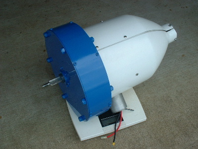
Shawn Yes the magnets are held on with magnetism! Is that enough?? Time will tell. Temperature rating is M (N50M), 100 C. I guess you could use thicker wire, I assume a lower voltage per turn though. I am just learning too. Well I tested the AXFX today. Very disappointing. 1) 100 RPM, star configuration, between phases, ? 15.5v AC ?. But fluctuating a lot. 2) 100 RPM, 3 phase, star, rectified, ? 21v DC ? Still fluctuating. 3) 100 RPM, 1 coil, while still connected in series with the other 2 coils, 3-4v AC. Suspected some magnets in the wrong orientation. So dismantled. Found 4 magnets in the wrong orientation. I don't know how that happened. Removed the 4 perpetrators and fitted them back on the right way around. Glued again and painted only those magnets. Reassembled. Tested again. 1) 100 RPM, delta on phase 1, 3 coils in series, 13v AC. 2) 100 RPM, star configuration, between phases, 22v AC. 3) 100 RPM, 3 phase, star, rectified, 31v DC. 4) 48v DC at 155 RPM. The magnet gap is 22mm. Trev @ drivebynature.com |
||||
| Gizmo Admin Group Joined: 05/06/2004 Location: AustraliaPosts: 5117 |
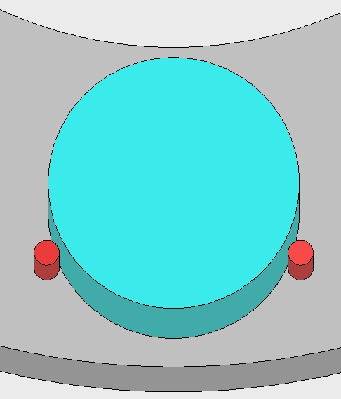
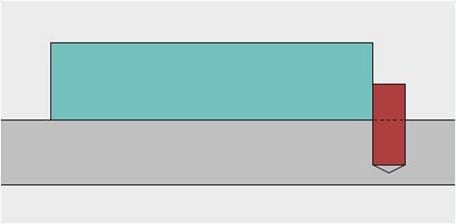
Hey Trev Yeah, I think you should secure your magnets. I've see a LOT of photos on Other Power where the magnets have come loose and slid out the side of the alternator. Remember, under load the coils are pushing magnetically against the magnets, they are trying to push them out of the way. On my own axial, if I ever get back to finishing it, I was going to use dowel pins to secure the magnets in place. Hopefully the pictures below will explain it. Each magnet should only need two dowels, at about 150 degrees apart from the center of the magnet. Ideally you could use 3 dowels per magnet, one on the inside. The dowel holes dont need to be drilled all the way through the steel backing plate. The dowels only need to poke above the steel plate by 3 to 6 mm, just enough to stop the magnet sliding. The steel plate is shown in grey, the magnets in bluse, the dowel pins in red. 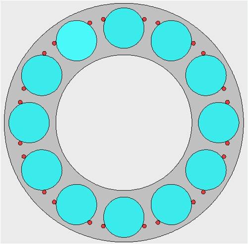
Glenn The best time to plant a tree was twenty years ago, the second best time is right now. JAQ |
||||
| Tinker Guru Joined: 07/11/2007 Location: AustraliaPosts: 1904 |
I would do that somewhat simpler than the precision drilling dowel holes method shown above. How about a piece of plywood, slightly thinner than the magnets and cut holes in it for the magnets to poke through. This can also come in handy as a locating jig when placing the magnets. The plywood needs to be encapsulated in epoxy to waterproof it before painting. The plywood (or any other non conducting suitable material - plastic? - only needs 3 or so screws to prevent the lot from sliding with the magnetic drag force. Regarding testing the magnet polarity, after assembling the lot on the steel plate place a 6mm ply sheet over the top. The N or S pole of a small bar magnet (Jaycar sells them cheap) can then be moved over the disk magnets to see if the magnet bar alternately gets attracted and repelled. If this does not happen alternatively the underlying disk magnet is the wrong way round. Klaus |
||||
niall1 Senior Member Joined: 20/11/2008 Location: IrelandPosts: 331 |
i think with dowels youd need to get the nipping pressure just right , the nickle coating is ridiculously thin ..one crack anywhere and the clock will start ticking down 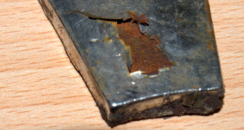
youd need to be pretty accurate with dowels but others have done it .... maybe half pot the mags in epoxy ? niall |
||||
MacGyver Guru Joined: 12/05/2009 Location: United StatesPosts: 1329 |
Trev Along the lines of what Tinker was saying about using thin plywood, take a look at this Link and you can see I did pretty much the same thing with my first ax-fx build. In the picture down the page a short ways, I used a hole saw, but in later builds I replaced the hole saw bit with a "forstner" bit as it cuts a more-precise hole. I slid the magnets over the plastic, then tipped an edge into the hole and finally slid the rest in with a minimum of "click" as each one snapped into position against the iron backing plate. This minimizes the likelihood of destroying the magnet's weak structure. On yet later builds, I found that if I stacked the magnets together, it allowed me to more accurately place a single magnet inside a holding hole without it snapping into position, risking its fracture. The rest of the magnets act as a kind of "handle" and allow easier placement. The plastic wheel was slightly thinner than the magnets' thickness so as not to interfere with stator clearances. Stacking the magnets or just using them right out of their box makes getting the orientation easy as well. All you do is alternate ends. First place a magnet from one end, then twist the pile 180 degrees and place the next magnet. This assures one is -N- face and the next one is -S- face so there's no mix up. Your build is awesome; keep it coming! Hope this helps you out some. . . . . . Mac Nothing difficult is ever easy! Perhaps better stated in the words of Morgan Freeman, "Where there is no struggle, there is no progress!" Copeville, Texas |
||||
| niall1 Senior Member Joined: 20/11/2008 Location: IrelandPosts: 331 |
hi Mac "Stacking the magnets or just using them right out of their box makes getting the orientation easy as well." erm...i think this could be picked up on wrong Mac.. approaching a rotor that has already got magnets of this strength attached with more than one in your hand sounds very dangerous , these things are in a different league , (even the 46.30.10mm N40 regular blocks are a handfull) i do understand what you mean and can see how it,d work well with baby neos but its just that someone might interpret it wrong with even mid sized mags (i.e. not look up your thread).....you only get one chance maybe a kind of "basic safe neo practice" thread would be worth having .. sorry if this seems alarmist but i have heard of an accident of a builder who got his hand trapped between two rotors that slapped together...  ..it kind off changes your perpective ..it kind off changes your perpective niall |
||||
JimBo911 Senior Member Joined: 26/03/2009 Location: United StatesPosts: 262 |
Trev In reference to keeping magents in place. It obivouis your machining skills are very good if it were me I would machine a hole or notchs to recess the magnets into the steel plates let's say an 1/8 inch (dont know in metric)add a small amount of adhesive and your good to go. Use that bad ass mill and your indexer like you did for drilling the other holes to help keep things neat and tity. This may help you sleep better at night when you hear mother nature blowing up a storm. Jim |
||||
| MacGyver Guru Joined: 12/05/2009 Location: United StatesPosts: 1329 |
niall1 My bad. I somehow figured everyone on the 4m already knows I build "toys" but you're right, someone new might get the wrong idea and pinch a pinkie or worse! Even the little fellers hurt when you give them just the right amount of flesh and leverage. The magnets in the link I set are 1" and they'll pinch the heck out of your finger. Thanks for the tip. . . . . . Mac Nothing difficult is ever easy! Perhaps better stated in the words of Morgan Freeman, "Where there is no struggle, there is no progress!" Copeville, Texas |
||||
| niall1 Senior Member Joined: 20/11/2008 Location: IrelandPosts: 331 |
i think i have a phobia about neos Mac..not the best around sharp tools either ...  niall |
||||
shawn Senior Member Joined: 30/03/2010 Location: New ZealandPosts: 210 |
Me again i do not want to pick any holes in your mill your work is great but one other thing i noticed is you only have 3 bolts holding your stator in place all the power the blades produce will go into them this was discussed on glens mill 3 is not many even if they were on the outside of the stator even worse on the inside you can tell me to go away if you like others might add idears best to talk now than repair later just for example mine has 6 bolts 16 mm on the outside of the stator and your mags are similar to mine. edit lol mine atually only has 5 bolts don't even know my own mill.  |
||||
| Gizmo Admin Group Joined: 05/06/2004 Location: AustraliaPosts: 5117 |
I agree with you Shawn. I was going to see if Trev had plans to strengthen this area before making a comment, but I do agree this area will need to be stronger than it is, or it will break apart. I used a 3mm(1/8th inch) plate on both sides of the stator, with 3 12mm threads to support and position the stator, and a further 6 8mm bolts to keep it all clamped together. 
Under load, those 3 bolts are holding back the full power of the turbine. Glenn The best time to plant a tree was twenty years ago, the second best time is right now. JAQ |
||||
Doug Regular Member Joined: 11/05/2010 Location: New ZealandPosts: 41 |
Hi all. Just another thought along the lines of Tinkers plywood suggestion. How about two disc's of 6mm Polycarbonate sheet to locate the magnets. It doesn't require any form of waterproofing, is very light and is quite literally bullet proof. Just a thought. Doug May The Power Be With You |
||||
| shawn Senior Member Joined: 30/03/2010 Location: New ZealandPosts: 210 |
Comon aussies trev might sell one of these to your neybour and all that have responded to this post have had a part in the building of it. trevs workmanship seems great there is just a few small bugs to sort out i would like to own a mill that the mags stay on and the stattor holds together! you do not need a newbie kiwi like me telling you how to do this.  he he he that should wake a few up!!! he he he that should wake a few up!!! |
||||
| Trev Guru Joined: 15/07/2006 Location: AustraliaPosts: 676 |
Thanks for all the ideas, the windmills keep turning. Shawn, I read that your magnets are similar, please tell me more, what grade, size etc. Did you have them glued with super glue and they came off?? I fiddled around with the rotors and discs and managed to get the magnet gap down 1mm, to 21mm apart. Scraped off some paint in the process, but whos cares, this is a test. I needed to know if closer magnet gap would deliver much increase in voltage. Well, not much. 100 RPM, star configuration, between phases, 24v AC. Up 2v AC. 100 RPM, 3 phase, star, rectified, 31v DC. The same. Suspect minor inaccuracies with measurements. So then I went the other way and increased the magnet gap to 23mm. And the voltage dropped. 100 RPM, star configuration, between phases, 21v AC. Down 1v AC. 100 RPM, 3 phase, star, rectified, 30v DC. Down 1v DC. Just proves I need to get the magnets closer. So dismantled. Because the stator had warped some when fibreglassing, hence the reason why I can't get any smaller magnet gap, I cut and ground a groove in it. This weakened it enough to push it flat. And then re- fibreglass, while held flat. 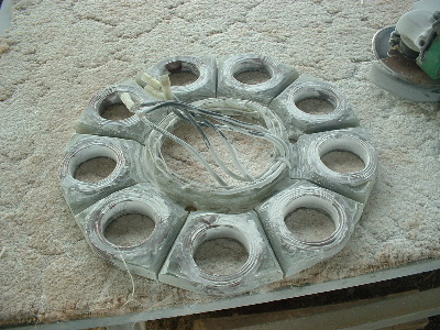 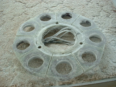
All is well, we will win eventually, but only as we learn. Trev @ drivebynature.com |
||||
| niall1 Senior Member Joined: 20/11/2008 Location: IrelandPosts: 331 |
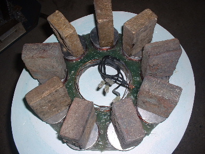
this mighnt be of much help ,but for whats its worth this is how i secured my mags 
the mags are half potted in epoxy ,(tacked on first with superglue) the reason for the extra expense was a little extra peace of mind... if the mill needs to be shut down /shorted in high winds it stops with a ker-clunk ..from about 300 rpm to 0 by the time you can look up ,its a heavy prop ,axials are like that , i dont think i,d trust super glue in the long term...especially with the damp weather we have here (thats what colors my thoughts ,peoples situations are different) you mentioned your earlier test of 48v at 155 rpm Trev ,what size prop do you hope to use ? if its a 3m/ish prop that doesent sound to bad at all ,if the alt is as efficient as it looks you might even have to open the air gap to play with matching the speed range of the prop , there could be lots of unknown options there yet its just an opinion ..... ..again very interesting thread niall |
||||
| shawn Senior Member Joined: 30/03/2010 Location: New ZealandPosts: 210 |
ok trev i strongly recomend using vinalester or westsystem epoxy to hold mags on would not recomend polester its the cheapest for good reason. the (done thing) now is to put a stainless band around the steel plate and mags then use this as a dam to put in resin some full up all the way to the top of mags i do nt think this is nessasary but i would bring it at least half way up. Im sure u can guess the kind of stress stopping a mill in high winds puts on things this trys to share mags sideways all 24 of them eventually they fly off. and worse in your case i think is your stattor all this stress is also on it and many a good solid stattor that has no holes and thick resin outside and inside the coils has shatterd under the stress these were also mounted on the outside of the stattor yours will be tryin to hold together from the inside glen had a good idear for that and i think it would be a absalut must do it might not even be enough for his size mill but without it death for sure. otherpower site is full of posts of mags comming off and stattor breaks heavy wooden blades may be a factor here giving that flyweel efect your lighter blades might help with this but best to be safe i think. my mags are 50mm diameter 15mm thick n52 and rated for 80 for heat. I will use vinalester and a stainless steel band to hold them on overtop of a powdercoated steel backing plate the resin sticks well to powdercoating. the stattor will be held in place with 5 16mm bolts on the outside this i think will hold together. 
none of this extra strenth takes away from your mills output and the extra weight is minamal once its up there mothernature can and will find its weeklink why make it easy for her? great looking mill niall bet that will hold together for ages and going by an earler photo you have learnt the hard way with mags. |
||||
| shawn Senior Member Joined: 30/03/2010 Location: New ZealandPosts: 210 |
here is a photo of my stator 16mm thick and steel stattor mount 10mm thick with 16mm holes drilled for bolts 5 bolts 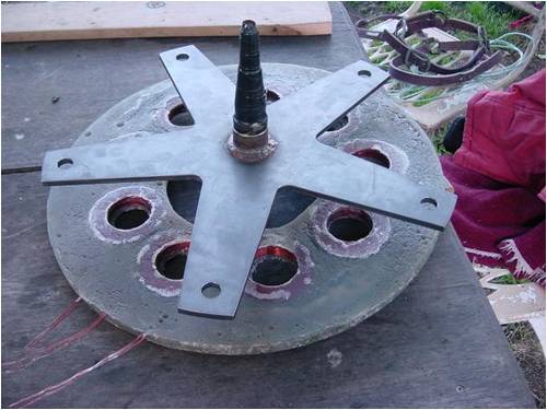
to try and hold this with 3 bolts on the inside of the stattor is asking to much. edit my postings are not intendid to critisize trevs/gordans/philms/glens designs they are great with many good points to them just trying to help a little. |
||||
| Trev Guru Joined: 15/07/2006 Location: AustraliaPosts: 676 |
The project is finished for now. On Sunday I took down the double F&P White Pointer, and put up the AXFX White Pointer. The AXFX is an all new unit, I did not use any parts from the old double F&P unit, which is now an icon, it was the first double White Pointer ever built. It has been up since 2006. Both units are the same, except the generator. Here are some final pictures. Magnet gap is 21mm and runs free after I re-glassed the stator back together. The cut-in RPM is a bit high, but I can add some caps or make another stator with more copper in each coil.........that will be a decision later. The weight is 28.8kg for the entire power head. The double F&P White Pointer power head weighs 20.4kg. 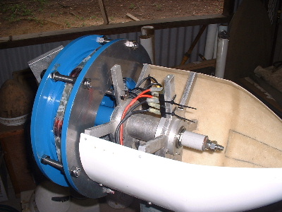 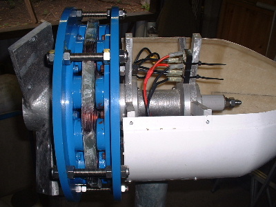
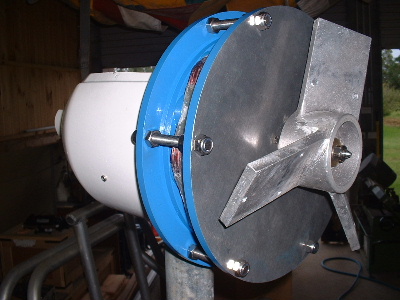 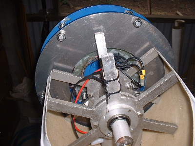
 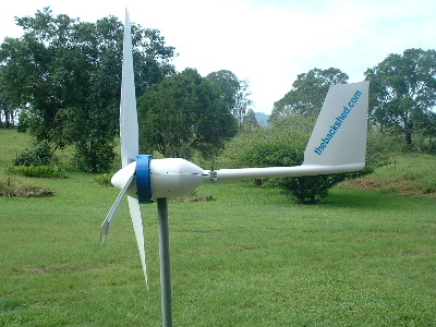
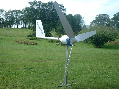 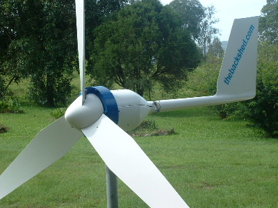
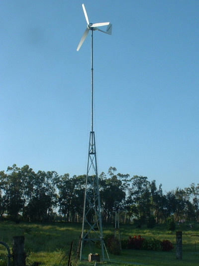 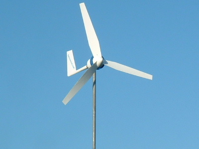
The AXFX now takes the place the Double F&P used to, in the picture as seen in Basicly Natural home page. 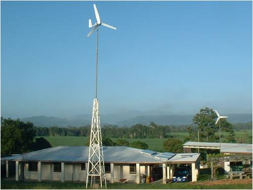
Trev @ drivebynature.com |
||||
| VK4AYQ Guru Joined: 02/12/2009 Location: AustraliaPosts: 2539 |
Hi Trev Very nice mate, as usual a professional job from you, now we await the performance figures. All the best Bob Foolin Around |
||||
| KarlJ Guru Joined: 19/05/2008 Location: AustraliaPosts: 1178 |
I've been holding back as I expected more comments from others as we've seen in the past on new and different AXFX builds. There is only one thing that really blows me away and thats your modesty Trev. Although you had a couple of go's at it tweaking etc you make it sound very easy. couple of mags ass about take it apart and rebuild it.....wow. It looks like the whole project took a day but of course it took plenty of effort. Top job look forward to some output figures -my guess is 5x the f&p dual. Regards Karl Luck favours the well prepared |
||||
| The Back Shed's forum code is written, and hosted, in Australia. | © JAQ Software 2025 |
