
|
|
Forum Index : Electronics : PSWGT-300 efficiency boost
| Page 1 of 4 |
|||||
| Author | Message | ||||
| Alasdair Regular Member Joined: 12/01/2011 Location: AustraliaPosts: 62 |
Hi all, I have purchased a couple of PSWGT grid tie inverters a few months back, and found a few bugs that are easily fixed by anyone who has a little electronics knowledge and can solder. The first problem is the stated efficiency of over 90% which is not possible out of the box, but can easily be achieved. The circuit uses a chopper inverter front end which develops the high voltage which is loaded onto the sinewave mains at line frequency, however in their (Powerjack) design, the input stiffening capacitor is only 4700uf, enough for the front end high frequency current demand of the chopper, however the secondary line frequency (actual current frequency) rattles this capacitor, in my case 50hz, and inducing a huge loss from any low impedance source, like PVs with long cable runs. My cure was to simply add 10000uF as close as possible to the input on the main board, I used heavy fly leads to allow it to fit in the corner of the case. I also found horrible levels of RFI pouring out the dc side of this inverter, which wiped out all AM radio for 100 metres radius. I cured this with two 0.22uF MKT caps tagged to the case and connecting to the positive and negative input terminals respectively. I have since had no radio interference at all, with nothing registering on my active FS meter, unlike pre modification. The peak efficiency is logging at 90-95% now, compared to 80-85% without modification. I also noticed R76 and R77 were showing signs of heat distress so I upped them from 1/4 watt to one watt metal film, they are 4.7 ohm each. They can be replaced without removing PCB. As my line voltage is 240v, I also added a panel mounted mains side fuse, tied between active IEC pin and the PCB, with double wall heatshrink. There is a circuit mounted fuse in place, but it is rated for 110v supply at 5A! The fuse I installed is 1.6A. The 5A fuse has my inverter to protect itself! I also tossed the supplid IEC power cables in the bin. The wire in these leads is about 0.1mm with plug pins fashioned from a jam tin. Another trick to lengthen life of this device is to never switch the mains on and off with DC present. The tracking will go out of sync and blow four mosfets on the high voltage side. With the unit plugged in, a power failure will not cause this fault, as supply loads will pull output voltage to zero. Remember.. Disconnect DC side first when turning off. All in all, it's a great little device, good value and cheap to boot. Amc-elec |
||||
| VK4AYQ Guru Joined: 02/12/2009 Location: AustraliaPosts: 2539 |
Hi Alasdair I use a few of these and I use a 250,000 cap across the input to get better performance and hold the sync on the windmill better, I have also found that a 470K or 1 meg resistor across the switch on the input voltage keeps the input caps partly charged and reduces the inrush current that can blow the input fuse, this is very important when using them for a load dump across the batteries. I don't have a problem with RF out as I think the external mounted 250000 cap kills it but I will add the suppressor caps you suggest for good measure. I will have a look at the resistors as you suggest. The main problem I have with them is getting to hot as the fan is a bit small and they tend to overheat when the temp goes over 34 deg, Also I have found several AC leads open circuit, so if anyone gets one and it doesn't work run a check in the continuity of the lead. The same goes for the 600 watt units. All the best Bob Foolin Around |
||||
| Alasdair Regular Member Joined: 12/01/2011 Location: AustraliaPosts: 62 |
I will add that resistor to mine too. I also noticed the temp getting a bit high, so I cut the three lugs on the end plate by using a holesaw (36 mm) as the three little slits provided restrict airflow, and I put spacer washers at the other end, creating a gap to let more air through, it required longer 4g screws. I also ran a bead of heatsink grease down each mating surface of the lid, effectively thermally coupling it to the case. This made a big difference and now at 230 watts (max panel output) it runs only luke warm. Amc-elec |
||||
AMACK Senior Member Joined: 31/05/2009 Location: AustraliaPosts: 184 |
Hi All I have got a 600 watt on it's way and I intend to use it a a dump load too. If you have a few photo's of the insides of them before and after mods would be good to look at. I did send Bob a PM a few weeks back and he did explain what he had done to them to get them to stop letting out magic smoke. The bloke over the road from me uses about 10 of the 300 watt units and he has poped alot of them too. AMACK *Note to self 1. Make it thick 2.Make it heavy. 3.Make it stronger than it should be. 4. Don't rush the first job as the second job will cost more and take mor |
||||
| Alasdair Regular Member Joined: 12/01/2011 Location: AustraliaPosts: 62 |
I'm not familiar with the 600 watt version.. as yet (my next purchase will probably be this model) but I'll bet the modifications listed for PSWGT-300, except burned resistors, will offer the same nett improvement. I am surprised at the slight lack of engineering with these units, as the mods are cheap and easy, and the bigger caps on dc side can only improve the slew rate of the mosfets by lowering their source impedance, this makes them bleed less energy and run cooler to boot. It probably comes down to cost/quality equation, divided by principles. I will try and get some photos up soon, my units are screwed to the roof truss in the shed, so a little difficult to access. I also built a solid state relay box tO be triggered by solar panel voltage, to avoid night time power leakage into inverter. This was quite dissapointing though, as I measured the standby consumption of the inverter at 4 watts, (17ma rms/240v) however the $25.00 opto 22 solid state relays still pass 13ma when off! I triple checked this, and sure enough it bleeds 3watts at night with solid state relay in off state. I save a whopping 1 watt, which equates to about 1000 years payback time. Amc-elec |
||||
| VK4AYQ Guru Joined: 02/12/2009 Location: AustraliaPosts: 2539 |
Hi Alasdair I found the same as you with the electronic relays and now use conventional relay for switching, it uses a bit more power when activated but then it is activated because there is to much power so who cares, not me. I use these little units as part load for the windmill and as dump load across the batteries and they work well in both places with a little TLC. They are built to a price with a reasonably good design for the money,and probably a couple of extra caps takes the bit of profit they make. When you look at what they are, you couldn't buy the components for what they sell for. Keep feeding in your expertise as i am sure that it will help a lot of us dummies. All the best Bob Foolin Around |
||||
| Alasdair Regular Member Joined: 12/01/2011 Location: AustraliaPosts: 62 |
Your dead right, despite their deficiencies, the value is still great. I could never build anything like that for under a hundred dollars. It's interesting that you are using yours for dump load / wind. The second one of my pair is to be driven from an antique (ww2 era) Lucas Freelite wind generator. I have to build a few bits for it, as it has a funny history and a few parts were lost. The output is claimed to be 20 amps at 12v, and having a mechanical regulator, I intend to tweek it's cutout voltage to about 18v to help maximize the MPPT of the powerjack inverter. I think I'll go mechanical relay too. I spent too much time and effort building a nice aluminium box with two GPOs, EMI filters big heavy lugs for dc in/out and 80A switches for dc isolation, and only one watt saving! I must have too much spare time.. Amc-elec |
||||
| VK4AYQ Guru Joined: 02/12/2009 Location: AustraliaPosts: 2539 |
Hi Alasdair Sounds like you did a real number on the controller when a headlight relay will do the job. I have found that the best for the GTI is 26 volts cause if you go to low in voltage the amps go to high to get the required wattage. I think you could dump the regulator off the old genny and just put a bit of nichrome wire for field ballast and a current limiter to the GTI, if it is the one I think it is you may need a second GTI to absorb the high wind power. 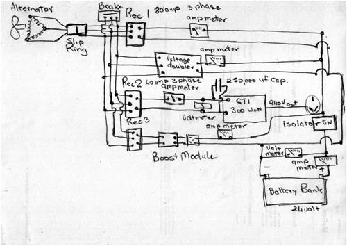
This is a mud map of my experimental setup on my mill, also have a 300 watt and a 600 watt GTI on the dump load on the battery pack using Glenn's dump load circuit. I have mine set to cut in at 27 volts and drop out at 25 volts, they will go to 30 volts but cut out on over voltage. Mine will draw 12 amps at 27 volts and a bit higher until it heats up. It just starts to conduct at 15 volts around 2.5 amps from memory. I have tried it on the solar but the volts go to high and it cuts out (24 volt system) voltage 40 on a good day need MPPT to the batteries, I got a 22 to 55 volt 600 watt unit but haven't tried it yet as we have had to much overcast weather. All the best Bob Foolin Around |
||||
| Alasdair Regular Member Joined: 12/01/2011 Location: AustraliaPosts: 62 |
Good idea, not so important to regulate at all with mppt. Just let generator push it out and GTI soak it up. I keep thinking as though I'll boil batteries dry. I could put a little voltage switch there to clamp it down in one our roaring fourties gales. Those powerjacks shut down over 24v, but I don't know if two GTI's will take out the 70 year old windings. The great wind debacle.. Mother natures foot on the accelerator pedal, and me with no brakes. Amc-elec |
||||
| VK4AYQ Guru Joined: 02/12/2009 Location: AustraliaPosts: 2539 |
Hi Alasdair You could put a switch mode current limiter in circuit to protect the windings if you think it necessary, but remember the volts are the thing going up not so much the amps so the watts go up but the current in the windings stays at a lower level. The GTI I have are rated at 14 to 28 volts so using them at 27 volts is within their rating and I found that they cut out at just over 30 volts, I have some rated at 22 to 55 volts but not much good unless I put them direct on the solar panels, as they go to 40 volts OC and loaded 34 volts where it works well but not to full output, it needs to get to 48 volts to do that. I think the MPPT system in them is a basic voltage Dependant current limiting device as they go to a certain amps then plateau at that but as the volts go up naturally so does the wattage. With the fragility of the generator it would be better to make a active furling system for high wind events as a dc generator could cook up if allowed to run wild in the wind. Dump loads only are a success to dump excess power when the generator is charging in it's normal range and the batteries are full, to short one out in high wind would be a disaster. If you are worried about the windings it would be a good idea to do a low voltage motor on the generator for a few hours to heat it and dry out the windings, then vacuum bag impregnate them with epoxy resin, it is a bit of a pain in the bum to do but will keep it alive for a long time. It would be a good idea to do the fields as well if you can get them out. They aren't as critical as the armature as they can be rewound easily. Have fun with all the fiddling. All the best Bob Foolin Around |
||||
| Alasdair Regular Member Joined: 12/01/2011 Location: AustraliaPosts: 62 |
Lots of good ideas there. Setting in the windings is definately a good idea albeit as you say, difficult. The generator was never actually used, the guy I bought it from purchased it a week before getting called up for the war, when he returned as an ex POW the mains power had been run past their property. With no need the generator, the head and propeller were put back into the shed, but the mounting cradle and tail with a ten foot pole were left attached to a tree, which sixty years on, grew to a height of about 50 metres. I think it is probably still there, a rusty yellow speck in the treetops. I declined his offer to fell the tree to retrieve those parts, as urban sprawl put houses all around, and the thought of explaining why half of a rusted out freelight wind generator coming through some unsuspecting residents ceiling made me leave those bits to the birds. I have made a cradle and sliprings, and I am thinking of making an active steering unit, that remotely detects direction and windspeed and steers the blade into or out of the wind as required. The beauty of this option is that I can use current limit switching to step out of wind, or just windspeed threshhold, with hysterysis and delay to stop hunting. Another bonus is that I can also do away with unreliable sliprings, make the rotator do 360 degrees in two blocks of 180, with some smarts to stop and rotate back around if wind direction moves past 0 or 360 deg point, eliminating cable windup. I also thought of dropping a centre pole through the mast so I can fit the steering motor and position sensor at ground level, with a shorter fly cable to do the twisting. This would make servicing much easier, put less weight at top of mast, and I will drop the long shaft onto a front hub from a front wheel drive car, without the cv joint, I can pass cables through this hole, there are four m12 mounting holes and well sealed bearings which will take plenty of thrust load, I'll also add an anti whip bush half way up and make the top bearing from molybdenum impregnated nylon to minimise maintenance. It may look a little wierd with no tail, but the benefits suit me well. Amc-elec |
||||
| VK4AYQ Guru Joined: 02/12/2009 Location: AustraliaPosts: 2539 |
Hi Alasdair Sounds a bit complicated for an old bugger like me, I have a old Chinese mill with no slip rings and use a bungee cord toed to the tail, it can rotate 2 turns then the bungee cord winds up and brings it back to normal. 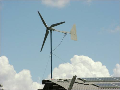
Note the bungee tied with precision and finesse onto the carefully fabricated tail extension. I use high quality bungee from a sail maker as it is purported to be UV proof, a bit crude but it works like a treat. With your system you may find it has torsional resonance in the inner tube to cause a resonance and make noise or worse destroy the head. Sounds like you had a win to get the new old generator and propeller like that, but if it has been laying around for years it still would to give it a low voltage run to warm it and dry out the windings. The link to glens little simple controller:- All the best Bob http://www.thebackshed.com/windmill/articles/TL084-Controlle r.asp Foolin Around |
||||
| Alasdair Regular Member Joined: 12/01/2011 Location: AustraliaPosts: 62 |
Brilliant. Bungee cord is the go. As they say simple is best. I should try that first. It'd save a lot of work, and at the end of the day it's only 200 watts, so probably never going to make much of a dent anyway. What do you think of offset furling with a sprung tailboom to allow the blade to blow out of the wind while the tail remains straight.. ish? Regards Alasdair. Amc-elec |
||||
| VK4AYQ Guru Joined: 02/12/2009 Location: AustraliaPosts: 2539 |
Hi Alasdair I have mixed feelings about furling, and in the past have left the mills run, as a bad furling device can and sometimes causes more damage. With my new mill I have been forced to revisit the furling issue as the structure of the mill is such that it cannot stand high speed operation from an electrical and a structural point of view. The original design of the furling didn't work as once the tail was extended to the point of reliable wind tracking it was to heavy to furl properly with the existing design angles. On Phills advice I have modified these angles and fitted a larger and lighter tail vane. The recent storms have been very severe with gusts fast enough to rip trees apart and blow things around the property. Due to the heavy rain it was like watching the mill through a milkshake so I couldn't draw any Hi Tech conclusions from the event, suffice to say that I could see the blades slowing on heavy gusts and re accelerating as the gust dropped back and all stayed together, some of these gusts where measured in excess of 25 ms before the lightning took out the weather station radio link, and it got worse from there, the fact that it did survive the event proves that it worked, whether it was at the proposed 15 ms maximum, where the generator is at full output or not is still open for proof. The angle setting I used was 5 degrees lay back and 10 degrees to the side with 4 inches offset on the mast head for a 2.8 meter blade This is a starting point for the next mill, but will have 5 inches offset due to larger blades 3.65 meter. I also reduced the weight of the blades to reduce gyroscopic loads After doing a lot of hands on static testing I believe these angles to be a good starting point for furling, and the offset to suit the blades bigger or heavier blades more offset, with a tail boom length of .7 the diameter of the blades. I have read many different angles for mills to furl from different authors and I believe that each one has merit for the blade alternator setup the author was testing, but the variability of our blades and alternators / generators doom us to confusion unless the exact same machine is created. http://www.thebackshed.com/Windmill/Docs/Furling.asp I plan to put a sliding weight on the tail boom to tune the response rather than a spring, due to the fact that Murphy breaks springs at inconvenient times, gravity is a bit more reliable. The other approach is to use a linier actuator to fully furl above 15 ms with a time constant built in to hold the mill furled until it is safe to resume normal operation. This is a a deviation from my KISS methods as I don't have much faith in electronics reliability in a less than ideal environment or any harsh environment for that matter. The old toggle furl on the water pump windmills is good if you can sit and watch, but Murphy's law of observation takes precedent there. Sorry to waffle on again. All the best Bob Foolin Around |
||||
| AMACK Senior Member Joined: 31/05/2009 Location: AustraliaPosts: 184 |
Hi All, I got my 600 watt grid tie invertor today in the post and went out the the battery shed to conect it up. All went well for less than 4 minuts and it started to make a arking noise and 10 seconds latter it went pop and magic smoke. The battery's were at 26 volt and it started up and voltage went down to 25.2 and it was pulling around 17.5 amps. I did as Bob said and conect the mains up and then the DC. Have been incontact or sent a EMAIL to the company I got it from but still waiting. Amack *Note to self 1. Make it thick 2.Make it heavy. 3.Make it stronger than it should be. 4. Don't rush the first job as the second job will cost more and take mor |
||||
| VK4AYQ Guru Joined: 02/12/2009 Location: AustraliaPosts: 2539 |
Hi Andrew Chinese magic smoke escapes easier, but I haven't had that problem with any I have tried, however some of the Chinese inverters have done that because the FETS where not held onto the heat sink properly loose screws and pressure brackets not fitted properly, don't like your chances on getting warranty as I never had any luck. The amps it was drawing is about right, compared to mine, look for brown holes in the components where the smoke escaped to effect repairs, if it was copious white smoke it is probably a faulty electro and hopefully only blown the supply fuse. All the best Bob Foolin Around |
||||
| Alasdair Regular Member Joined: 12/01/2011 Location: AustraliaPosts: 62 |
That doesn't sound good. Power Jack do seem to do the right thing with warranty. Have you peeked inside? The arcing sounds like a dry joint or a stray speck of solder, or worse an insulation breakdown in the chopper transformer. The pop will probably be a MOSFET or two going west. Unfortunately switchmode stuff can do some spectacular things with the energy available at destruction time. If you fix it yourself, do a ring test on the transformer ( if you have a cro) I have tracked faulty (layer shorted) transformers this way. A little unconventional, set the cro to ac with fairly high V/cm vertical, put a couple of volts DC across primary first with cro on same winding, disconnect dc and look for a back emf spike and ripple several times magnitude in voltage, no back emf will show a shorted winding. A crude test but it can save replacement semiconductors before powerup. You can also test secondary the same way. Bob, your information is very useful, and I'll take it into account. I only have a two blade aluminium propeller, which by it's very nature doesn't appreciate sudden changes of direction, as the gyroscopic effects put compounding loads on the blade roots, as I'm sure you know. Your idea of a weight is one way I could help overcome this, a giant tail would resist sudden movements on one hand, but force sudden movements in strong gusts. I even thought of fitting a car starter ring gear to the head, connected to a pinion gear with a flywheel of some sort, it would dampen sudden changes, but offer little resistance to eventual direction. Another trick I thought of trying was to use a gas lift strut in place of a spring, I have a couple in my junk box and they have the bonus of damping sudden movement, and retracting slowly. Regards, Alasdair. Amc-elec |
||||
| AMACK Senior Member Joined: 31/05/2009 Location: AustraliaPosts: 184 |
Hi Bob I have sent the seller an EMAIL and they want photos? Of what I am not sure but I do not think it was a fuse that went POP as it was quite loude and is has that lovley bakalite smell. Even if I can get a repair kit out of them as I have not taken it apart yet to see.  AMACK AMACK
Everything I have touched latley has turned to SH*T. *Note to self 1. Make it thick 2.Make it heavy. 3.Make it stronger than it should be. 4. Don't rush the first job as the second job will cost more and take mor |
||||
| Alasdair Regular Member Joined: 12/01/2011 Location: AustraliaPosts: 62 |
Bob, have you thought about trying a tapered coupling to hold centre? The generator/alternator can sit on a shaft sliced at an angle with a centre locating pin, the weight pulls it to centre, as any deflection must lift the gen vertically, the amount of lift is determined by sleeve cut angle and diameter. You'd need to weld a lug at 90 deg to limit deflection. Pack it with grease and slip an inner tube over it. That chinese magic smoke you speak of does escape easily but Japanese magic smoke is full of mystery, and very expensive. I once fitted a $95000.00 Sony projector into WMC and got to witness a magic smoke show which included a fireworks display and a small scale thunderclap. I distincly remember the stunned silence as all looked on .. mesmerised. The GM then asked that most enlightened question.. Is that normal? YEP! Amc-elec |
||||
| VK4AYQ Guru Joined: 02/12/2009 Location: AustraliaPosts: 2539 |
Hi Alasdair A steering damper of a motorbike works well and is adjustable, $30 on fleabay. That is a bit like cam activated furling, unless you have a groove to control the action the gyroscopic forces could make for different results than wanted. Andrew If they want pictures send them a picture of you holding the smoking Inverter with an unhappy look on your face, from the bad smell described it sounds like an arc over on the board in the HP section. I went down that track with an inverter and gave up in the end as they sent me all sorts of bits they had laying around but nothing to do with the problem, sorry for no good news, I found however they are really useful for interesting spare parts. You may get some warranty if you really annoy the hell out of them, but ask for a new unit not a repair kit. All the best Bob Foolin Around |
||||
| Page 1 of 4 |
|||||
| The Back Shed's forum code is written, and hosted, in Australia. | © JAQ Software 2026 |
