
|
|
Forum Index : Windmills : Yet another axial
| Author | Message | ||||
| VK4AYQ Guru Joined: 02/12/2009 Location: AustraliaPosts: 2539 |
Hi Hugh That is using your head, if we could do something the same it would be good for the group. All the best Bob Foolin Around |
||||
| Gizmo Admin Group Joined: 05/06/2004 Location: AustraliaPosts: 5019 |
For those waiting for some figures, I've been a bit too busy. At a glance, its good for 150 watts at 500RPM. I've built a test setup using a treadmill motor and speed controller, and its got enough power to drive the alternator. My problem is accurately measuring RPM without spending too much money. I have a couple of CRO's, but these are not much good at quickly measuring frequency. I had a Hz function on my multimeter, but its no longer working. I have a frequency meter but it wont settle down, there too much RF from the stator ( diode switching ). I have a Oatley K117 optical Tacho, but it needs calibration/repair and Oatley no longer sell the kit, so I cant find a copy of the PDF anywhere. I do have a Maximite, but I dont have the time just now to write a quick program and build a interface. Its end of month, so I got a bit of work to do and invoices to post out, give me a few days and I'll see what I can come up with to measure frequency/rpm Glenn The best time to plant a tree was twenty years ago, the second best time is right now. JAQ |
||||
| Gizmo Admin Group Joined: 05/06/2004 Location: AustraliaPosts: 5019 |
Stuff it, had to go give me-self an idea didn't I. I wrote a little program for the Maximite computer to act as a tacho. The Oatley K117 kit does partly work, the optics and trigger circuits, a LED flases as a bit of tape stuck to the alternator passes the optic sensor. Good. So I connected the LED wires to a optocoupler attached to a Maximite. Then I wrote a program to time the LED on and off states, and display the results on a LCD display. 
It displays total cycle ( 1 revolution ) duration in miliseconds, the duty cycle in percent, the frequency in Hz and the RPM. The information is updated each revolution of the alternator. Works GREAT 
This is the test setup, sorry about the poor image quality. 
Its good to get a win occasionally 
Now I can go and take some readings. I'll post a thread about the tacho software and circuit in the microcontroller section in a day or two. Glenn The best time to plant a tree was twenty years ago, the second best time is right now. JAQ |
||||
BobMann Senior Member Joined: 30/06/2011 Location: United StatesPosts: 134 |
Hello It looks good you build a great axle flux motor. I wish you guys were a bit closer I would love to but a team together to build the next gen of power motors. Bob Mann |
||||
| Gizmo Admin Group Joined: 05/06/2004 Location: AustraliaPosts: 5019 |
Some figures 
I think it would work best as a 24v alternator, that is 24v Star 24v Battery, with a high speed set of blades. It makes 170 watts at 500 RPM, and you could see closer to 250 or more in strong winds. Glenn The best time to plant a tree was twenty years ago, the second best time is right now. JAQ |
||||
ChrisOlson Regular Member Joined: 19/01/2010 Location: United StatesPosts: 60 |
Looks like it would be a good match for a 1.5 meter three blade rotor. Of if you wanted to get a little more swept area and still get the required speed you could use a 1.7 or 1.8 meter two blade rotor to drive it. -- Chris off-grid in Northern Wisconsin, USA |
||||
| VK4AYQ Guru Joined: 02/12/2009 Location: AustraliaPosts: 2539 |
Hi Glenn I have some multi blade high speed blades if you need to try some you can have a lend to see if they work out, can do 6 blade five blade 3 blade and 10 blade about 1.6 meters dia. All the best Bob Foolin Around |
||||
| Gizmo Admin Group Joined: 05/06/2004 Location: AustraliaPosts: 5019 |
Thanks Bob, but unfortunately it will be like 6 months to a year before I have a place to fly it. Besides, I've had a rethink, and I want to make another stator. The standard side by side coil arrangement is OK for Neo magnets and flat stator moulds, but I have weak ceramics and the tools to make a stepped mould. And someone made the comment about "empty space", and he's right, there is a lot of empty space where a magnet is passing over the stator, inside the coils, and there is nothing in the magnet flux path. Overlapping coils is the solution. It ensures the magnets are always passing over copper and generating power. But it means the stator has to be thicker in parts so the coil bundles can pass over eachother. I can do that, with a bit of CAD work to get everything positioned correctly and the CNC to cut it out. It also means I have 8 coils per phase instead of 4, 24 coils total. Since I have twice the number of coils, they only need half the turns to reach the sme voltage, 70 turns instead of 140. 70 turns will fit into a smaller space, so I can make the stator thinner, down to 6mm thick. That means I can brings the magnet plates closer, 8mm apart instead of 14mm. That gives a more intense magnet field, increases the volts per turn, and I only need 55 turns per coil. So I've got more copper under magnets, and my coil resistance will be lower, which should mean more power. Back to the workshop. 
Glenn The best time to plant a tree was twenty years ago, the second best time is right now. JAQ |
||||
| VK4AYQ Guru Joined: 02/12/2009 Location: AustraliaPosts: 2539 |
HI GLEN Looks a bit complex for an old bugger like me, I would be putting two more magnets per group to get better spread or using the 50 x 50 x 20 as Hugh got for his, reason being that when you get all those coils in there it will reduce the strength of the stator considerably, unless you use the outside as the main reinforcement and that would mean more air gap and reduced output again. Anyway all sounds like good fun. All the best Bob Foolin Around |
||||
| ChrisOlson Regular Member Joined: 19/01/2010 Location: United StatesPosts: 60 |
I already built one of those with 50 x 50 x 25 mm ferrites - a 12 pole 36 coil. It didn't make any more power than the flat 16/12 or 12/9 arrangement. Just because these ferrite magnets are weak doesn't mean you can't make power with them. You have to think outside the box a bit and forget all the "conventional" designs. Keeping the air gap very tight is important and it's easiest to get the air gap tight with a flat coil arrangement. Because you have to use more turns of wire with the ferrites, putting more coils in series helps get the voltage, hence the reason I used dual single phase stators stacked and skewed 90 electrical degrees to build a two-phase machine. To get the internal resistance down you have to forget using the wye configuration and use either delta or IRP, and wind with big wire. Hugh and I disagree on this, but I"m the only person who has ever built a solid 1.8 kW ferrite axial generator for a homebrew turbine. Hugh likes the wye configuration. But after I tried four different configurations of it, I arrived at the conclusion that if you're going to build a polyphase ferrite generator all contained in one stator, and get output comparable to a neo, it's going to be one bloody big and heavy unit. The output of an air gap axial is determined by only two things - rpm/volt and internal resistance. If you want more power you have to reduce one or both of those. If you put the pencil to it and do some figuring, you only got so much flux density in the air gap and adding more coils in series to build an overlapped coil stator helps get the voltage with less turns. But the extra distance in coil interconnects eats up any perceived advantage over the flat arrangement. You actually end up using more wire per phase when you go to the overlapped coil design than you do with the flat. Hugh and I had an extensive discussion over this when I did it, and Hugh had long suspected that was the case. But I proved it when I built I the thing. I also tried a 10 pole 20 coil two phase unit in one stator. I ran into an immediate problem with that configuration - I couldn't get big enough wire in it and keep the stator thickness down to 12-13 mm. In the end I ended up with the dual stator unit. It makes the target 60 amps @ 30 volts in a 78.8 lb (35.7 kg) package. To achieve that output (same internal resistance and rpm/volt) in one stator would've yielded a generator almost 3x the weight and about 2.5x the size. And once you start increasing the size, the runout tolerances on the rotors have to be increased, meaning you'll have to run a wider air gap to prevent stator/rotor contact in real world operation. You can machine rotors +/- .04mm, set a tight air gap and bench test it and it will work fine. Put it on a turbine and it'll hit the stator and damage it. BTDT. So I allow at least 2.5 mm clearance between the magnet faces and the stator on 280mm rotors to prevent contact in real world operation because things flex under tremendous loads at high output on the turbine. The bigger the rotors, the more tolerance you have to allow. The more tolerance you allow for axial runout, the more wire you have to add to compensate for reduced flux density with the ferrites. It's a vicious circle. At any rate, really good project, Glenn! I look forward to more of your testing results. -- Chris off-grid in Northern Wisconsin, USA |
||||
scoraigwind Newbie Joined: 23/09/2009 Location: United KingdomPosts: 21 |
I have to say that this is contrary to the facts as I know them. I have done a page comparing the material weights and costs of 2 alternators built to my design style (Recipe Book pattern) and the single stator one uses less material and is more efficient. It follows from a basic understanding of the theory. And the rotor doesn't even have to be a lot larger diameter to achieve this. If you put the magnets onto two different stators you lose half of the voltage you could have had in each coil. I put the story on a page on my blog site here http://scoraigwind.co.uk/?page_id=953 Hugh Piggott |
||||
| ChrisOlson Regular Member Joined: 19/01/2010 Location: United StatesPosts: 60 |
|
||||
vawtwindy Newbie Joined: 23/10/2010 Location: IndiaPosts: 31 |
Glenn, here i need to point my fingures to another forum out here. http://www.vawts.net/t45015767/foamy-vawt/?page=3&sort=newes tFirst 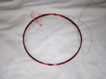
Hope this could be helpful for you. Hugh/Chris/Glenn/Bob, can you please bookmark the above links too. some discussions are pretty good in that forum too.. PS: Caleb from Vawts.net, i am sorry to use these pictures here. |
||||
| Gizmo Admin Group Joined: 05/06/2004 Location: AustraliaPosts: 5019 |
Thanks for that link vawtwindy, very interesting. I've had to put mine on hold for a short while, I've just bought some land and need to get my old Southern Cross farm windmill back into action to pump water. Glenn The best time to plant a tree was twenty years ago, the second best time is right now. JAQ |
||||
| scoraigwind Newbie Joined: 23/09/2009 Location: United KingdomPosts: 21 |
I have great admiration for what you are doing Chris, but I just needed to correct your allegation that a single stator had to be 2.5 times the size. I doubt if we shall ever agree on this but I have given an example of two alternators using the same size coils where the single-stator one uses less magnets/copper and is also more efficient. It can put out higher power in relation to the power that is used to drive it. You have reasonably pointed out that even though it's more efficient it will get hotter due to having less surface. It's losing less energy but it has to lose it over a very small surface area. Or I think that's what you were driving at. And it is true. I played with that aspect in the design and checked out how much bigger it had to be to be able to use the same energy dissipation over its surface. By increasing the larger disk size to 430 instead of 400 mm I can fit 2 wires at 1.4 mm diameter into the coil same as the dual stator machine. It still uses less copper overall, the steel disks are ony 15% heavier, and the resistance is down to 0.4 ohms compared with 1 ohm for the dual-stator version. So the single-stator version wins in every way apart from having larger diameter. The rotor is 1/3 larger diameter than with the dual alternator. And it will also stall sooner, due to being more efficient but I'd prefer to have a series heater in the shed (or my office) rather than overheating the stator on the windmill. If you were to build a ferrite alternator with 2 rotors 1/3 larger, then you would see the same benefits. If you were to take the materials that you put into the dual stators you and make a single stator machine then you could discard the gearbox and use direct drive. But there is no point, since ferrites are cheap and you like your dual stator. My agenda is to ensure that readers understand the pros and cons properly. Hugh Piggott |
||||
| ChrisOlson Regular Member Joined: 19/01/2010 Location: United StatesPosts: 60 |
Absolutely, and it's better to always have differing viewpoints and opinions. That's why most modern machines and devices in the commercial world are designed by teams of engineers instead of one person. When I said that I was referring to a direct drive design vs the geared unit, however there are other points too. I would like to comment a little further on this, simply because we do not agree 
. I would have to review your design criteria a little more to determine if the design in your blog applies to ferrite magnets (I suspect it does not but using the same flux density with two designs should yield accurate results). With neos where you can pack a lot of flux density in a small package I do not think a dual stator design is valid. However, using ferrite magnets is a different story. On the resistance values, for instance, you specify a 1 ohm resistance for the dual stator vs .4 ohm for the single, and I wonder about that. The effective internal resistance of the 13G generator is about .31 ohm in dual stator configuration. This is because it is IRP, two-phase (90 degree electrical separation) so the effective internal resistance of the unit is half that of one stator. Since I am the only one in the homebrew community that has ever built a turbine and generator combination with ferrite magnets capable of 60-65 amps continuous output on a 24 volt system, I would challenge someone to match it in a direct drive single stator unit using the same 50mm x 50mm x 25mm thick ferrite magnet blocks. I think you will run into two problems when you attempt it - cooling capability, and size and weight. The bigger the size, the more cooling area you have. But you are going to have to use a delta or wye three-phase configuration (presumably) so your coils are going to be very thick - OR - the stator is going to be very large. Once you get to a very large diameter stator you are going to have problems with the generator rotors contacting the stator, even with a very, very slight amount of "play" in the bearings of the machine. There are many other considerations but in the interest of brevity I will only say I have looked at this with ferrite magnets and a very large single stator design is not practical because it won't hold up on the tower. Someone is going to have to build one and prove me wrong before I'll believe that it can be done and match the performance and reliability of the machines I have built to-date. Regards, -- Chris off-grid in Northern Wisconsin, USA |
||||
| scoraigwind Newbie Joined: 23/09/2009 Location: United KingdomPosts: 21 |
It's strange to consider that it would make a difference whether we are talking about neo magnets or ferrite magnets because I am talking about the basic relations between magnets, coils, speed and voltage. Using weaker magnets will alter the numbers, but the relative performance will be the same. By the way when I mentioned resistances in my design we were talking about a 48 volt machine so the resistances tend to be 4 times higher than in your 24 volt example. In your case you use gearing to substitute speed for flux, and catch up with a similar performance to a neo alternator of the same size. Another way to have done that would have been to have used twice as many magnets on the rotors - in other words put them all on a single alternator instead of using two. This would have given you an alternator with the exact same characteristics at half the rpm speed (and I am not just expressing an opinion, that is a basic law of physics). Or if you want to go at the double speed (which does make sense because you can reduce the amount of costly material you will need) then simply increasing the number of magnets by 50% would easily achieve that. In other words 15 magnets per rotor in a single machine would do the job. Now you tell me to build one and show you, and so you win over me there because of course I would not build a chain drive upratio gear and I would not wind it IRC or dualphase singlephase etc. And so we can't make a practical comparison, and as a practical man you will not listen to my theoretical reasoning so we have to leave it there. But I hope that I have managed to explain to others why it makes more sense to put all of your magnets into a single alternator rather than to split them. Larger machines are simply more efficient. Hugh Piggott |
||||
| ChrisOlson Regular Member Joined: 19/01/2010 Location: United StatesPosts: 60 |
Hi Hugh: yes, and this is also true. However, with the ferrites it takes a lot more turns of wire to do the job. There is a limit to how big (thick) you can make coils and fit big wire for big machines. Building a ferrite generator for a smaller turbine is not really an issue. But when you get up to 4.0 meters or so in size, the generator has to be able to handle the power spikes and continuous output of the rotor. And again, this is true. The theory behind design has to be applied in the practical realm. And that's many times where engineering theory doesn't hold up. Many years ago when I went to work for Cummins as an apprentice mechanical engineer I was ready to change the world. I knew it all because I was fresh out of college and could solve any problem with theory. The first week I was there a grizzled old project engineer sat me down and told me, "Son, there's the way the book says that it SHOULD be done. But when you go to the shop and build it there's the way that it CAN be done. The two are rarely the same." I never forgot that simple lesson delivered by a man with years of practical experience designing and building some of the best products in the power generation business that exist. So when I look at large ferrite machines I apply my practical knowledge on what I know works and what doesn't. Can a large ferrite direct drive machine be built? Obviously, yes. Proven has done it for years. Is it practical, and will it last in a homebrew version of the axial generator? No. The diameter of the stator and rotors gets too large and heavy without going to a different design on a thru-shaft like Proven uses to more accurately control axial runout on the rotors to prevent contact of the rotating assembly with the stator. And that being said, the units that Proven builds ARE very big and heavy. I did work out a direct drive design for the 4 meter turbine and it would weigh over 2.5x what the unit I built weighs and be over 2.5x the size (diameter) to fit the same ampacity in it. By building the lighter and smaller geared unit I add about 22.5 kg of steel to the total weight of the machine in gearbox components. But in the end have a machine that is still approximately 32-33 kg lighter than you could do it in a direct drive version unless you used exotic materials such as aluminum or titanium. When you add mass to a wind turbine, adding it in the form of cross section in critical stress areas improves longevity of the machine. Adding it in the form of the generator increases stress on critical components like bearings and shafts. So it is important for folks to know that we are not comparing apples to apples. I am building very high performance machines with engineering criteria applied to longevity and stresses on the machine to make it reliable with the best performance curve possible. My design is more than just how many magnets I use, etc., because I start the design with goals in place as to what sort of performance I expect from it, then keep tweaking it until I get there. If I were to apply my goals to a direct drive version of a 4.0 meter axial turbine with ferrite magnets, looking at stress areas in the turbine and tower gets quite frightening when you start considering slinging 600+ mm 12mm thick generator rotors at 400 rpm. You have to throw a lot more iron at the problem to get it to last and hold up. And to even install the thing on the tower stub requires heavy lifting equipment that is usually not available in the remote locations where these turbines are used. And that's the practical considerations. Regards, -- Chris off-grid in Northern Wisconsin, USA |
||||
| scoraigwind Newbie Joined: 23/09/2009 Location: United KingdomPosts: 21 |
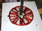
Ten years ago I had never handled a neo magnet and all the alternators I built had ferrite magnets. Mostly they were small axial up to 200 or 500 watts maximum continuous output. I also designed the AWP alternator which is a 1000 watt radial flux alternator. That has been quite a reliable unit over the years but hard to manufacture due to the laminations and also prone to overspeeding since the output current is limited by internal impedance. Going up in size my first attempt was to scale up the AWP alternator which already weighed 70 kg. I built one using a truck wheel as a magnet rotor and got about 5kW at 300 rpm using that but again it had overspeed problems and the stator was prone to insulation failures and a nightmare to rewind. 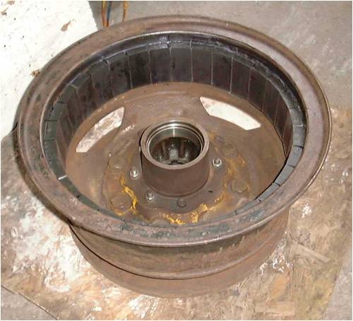
This was our 'nirvana' project that is described a bit on some very old pages on my old web site here http://www.scoraigwind.com/nirvana/page1.htm This describes the first axial flux alternator we used on this turbine. Actually we beefed it up twice before we were finally happy with it and the magnet disks ended up 660 mm in diameter with 32 magnets 70 x 30 x 10 Neo. I am not sure how much of this I documented on the old site. The blade diameter is 4.8 metres plus a silly triangular bit at the tip like a Proven. I am about to try a larger diameter. Big heavy alternators are a pain to move around but once they are up in the air they are very nice - slow and powerful. There are certainly some practical difficulties but we found that using a tripod and a chain hoist helped to reduce the pains in the spine. 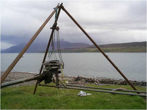
If you back a trailer up to the head of the tower you can swing some pretty heavy parts over into position using the chain hoist attached to the tripod. I am not sure if we'll end up building humoungous ferrite axials like this in the future. For now I still have a good stock of neo magnets, but when they run out I am not sure if I am going to want to throw silly money at more of those short-lived wonders. I am not a mechanical engineer and I don't see myself building chain drives so it'll be direct drive for sure. However I'll probably be shy of the very high power outputs and settle for low wind performance and a good capacity factor rather than build hugely heavy machines to cash in during less common winds. I hope that I have not been too shrill and dogmatic in my condemnation of the dual stator alternator, but sometimes it's frustrating when you can see something as clear as day but can't seem to communicate it. It's a bit like the vertical axis thing, and in the end you have to shut up and let people get on with doing what they want to do and just head for the workshop and do your own thing that makes sense to you. Hugh Piggott |
||||
| Gizmo Admin Group Joined: 05/06/2004 Location: AustraliaPosts: 5019 |
The F&P Smartdrive based wind turbines can also suffer from over speed, due to their impedance at higher RPM's. They will survive the event, though the rest of the machines is certainly strained. I think the radial flux layout needs to be revisited. I remember looking at your drum brake design many years ago Hugh and thinking it had some good features. There are some advantages to the design, especially the addition of iron to make the best use of the weaker ceramic magnets. However making laminations is beyond the ability of most home workshops. But a few years ago there was a lot of discussion in the Seeley motors. Ceramic magnets, open copper windings, and a iron backing. Power figures were respectable. http://www.thebackshed.com/forum/forum_posts.asp?TID=646&KW= seely But there were some mechanical limitations that eventually killed interest, it just didn't lend itself to use on a windmill. The Seeley did have one design feature worth thinking about, its iron backing was made up of steel wire wrapped around a plastic former. Unfortunately the wire coils where not insulated from each other, so there where some eddy losses. Building from scratch, you would insulate the wire ( etch, paint, etc ) before winding. I do think using this approach would turn the radial into a home workshop project, based on a drum brake, with the stator built to suit. Glenn The best time to plant a tree was twenty years ago, the second best time is right now. JAQ |
||||
