
|
|
Forum Index : Microcontroller and PC projects : Hardware Standards
| Author | Message | ||||
donmck Guru Joined: 09/06/2011 Location: AustraliaPosts: 1310 |
Cap'n Bill, or anyone who knows. A supplementary question, or should I phone a friend? If we wanted an extra gap between Arduino boards because of component heights etc, could we just stack it up with bare Shield Stacking Headers as spacers? It looks like it will work this way, but wanted to make sure. As the connectors top and bottom of this spacer are soldered in, I guess the strength in the stack is still there. Don't want to miss the obvious gotcha trick. Cheers Don... https://www.32v8.com/1 |
||||
elproducts Senior Member Joined: 19/06/2011 Location: United StatesPosts: 282 |
Don Wrote: >I still need the height of the black socket female section, and the length of the male tails, as my Chinese Lady >(supplier) doesn't know what an Arduino is. So if anyone can help there, it would be appreciated. The link to the data sheet is here: http://www.sparkfun.com/datasheets/Prototyping/Connectors/18 688.pdf The Arduino.cc site has all the gerbers for the pin layout. The two 8-pin connectors have non-0.100" spacing between them which means you can't build a shield out of standard protoboard. Apparently it was a gerber file mistake that stuck. Gerber file links are on the page below. http://arduino.cc/en/Main/ArduinoBoardUno www.elproducts.com |
||||
stuarts Senior Member Joined: 15/06/2011 Location: AustraliaPosts: 194 |
Quick question, well actually a couple and a comment. On an Arduino, what voltage range are the analog inputs. Is there an incompatibility with Maximite as Maximite allows only 3.3v. Assuming we use some of the Maximite analog capable lines for digital, what voltage range do the digital lines on Arduino support. A comment, it seems that the Arduino we lose 4 analog inputs. Just making sure that Arduino shields will work without level translators or protection. Stuart Time is nature's way of keeping everything from happening all at once. |
||||
| stuarts Senior Member Joined: 15/06/2011 Location: AustraliaPosts: 194 |
Don, my guess is that the .0413 could be the dimension of the pins. Just over 1mm square. Stuart Time is nature's way of keeping everything from happening all at once. |
||||
| stuarts Senior Member Joined: 15/06/2011 Location: AustraliaPosts: 194 |
I'd like to propose that when Don gets a Maximite to Arduino converter/baseboard going, that it gets called the Donduino. Stuart Time is nature's way of keeping everything from happening all at once. |
||||
| donmck Guru Joined: 09/06/2011 Location: AustraliaPosts: 1310 |
[code] I'm sure you hardware weenies will figure out ways to make as many MM pins as possible both available and signal compatible with Arduino shields. [/code] If I, or any one else was to say, "There is no way we are getting on the Arduino Bus!", 3.5 milli-seconds later "hardware hackers" as we used to call them, would be making adapters to see if they could get it to work. Hacking seems to mean a "software hacker" these days. Time for a little bedtime story. First time I have told this story in an open Forum. All sitting down Maxiteers? I can see Jimmy, and Annette, and Darlene, and Cubby. Hey there is Cap'n Bill and Chuck, right in the front row. Once upon a time, a long time ago when Don had hair, (circa 1978-80-ish) a friend of his, an electronics school teacher by the name of "Rob Mc--------", who is still tied up in the teaching game, and at the same institution I might add, came to him with an idea he needed assistance with. GMH (a subsidiary of GM in the U.S.) Port Melbourne Australia, wanted a vehicle loom tester, and head office Detroit wanted $40K for it. A tidy little sum at the time. A tidy little sum today. My figures may be wrong, as I have found when writing about details of stories that took place 30+ years ago. For a minuscule sum, we hacked a TRS-80 to do the job. Rob got a motherboard he purchased as a spare part, and I hacked the Roms, so that the video routine was stripped out, just in case anyone ever plugged a monitor into this mother. I also stripped out all readable text strings, and embedded our BASIC program into the Roms, so when it was powered up, it auto ran the embedded auto.bas program. Sounding familiar? We made up a simple front panel with a few LEDs and switches on it, buttons like "walk" and "don't walk", or whatever it was. No, that was for street crossing signals, wasn't it? :-) As we say in OZ, and "Bob's your uncle". It worked like this for many years. Interested parties that may want to sue us today for copyright infringement could be GMH, Tandy, and Microsoft. Level II Roms for the TRS-80 was one of Bill Gate's early works. But as it was 30+ years ago, and they all have bigger fish to fry, then this wouldn't happen, would it? Perhaps it is just a bed time story, and I made it up, and it is all hearsay evidence. You be the judge. :-) BTW Mick G. sighted the device when he worked at GMH years later, but he is a habitual drunk, so I wouldn't believe him either. He has cost me a fortune drinking my beer every Friday night for....... how many years Mick? I see a message coming in from Chuck and others, so I'll collate this with what I have. Cheers Don... https://www.32v8.com/1 |
||||
| stuarts Senior Member Joined: 15/06/2011 Location: AustraliaPosts: 194 |
Don, I remember the other one. It had a screen and showed all connections as good or bad. It was designed to test the Camira instrument panel harness and that was all. Admittedly that was probably the most complex one whe had at that point. There were also a few simpler ones that someone had cobbled together that used some simple TTL chips to scan across all the wires in the simpler harnesses. They were a nightmare to fix as they had all been wired point to point with wire wrap wire. Evey wire in the unit was wirewrap. Even the ones going to the front panel. You only had to look at it and they broke. The bigest problem with all the electronic testers that they used was that they didn't use real world current flow so they would test a harness as good when it wouldn't cope with the current when put in a car. Stuart Time is nature's way of keeping everything from happening all at once. |
||||
| donmck Guru Joined: 09/06/2011 Location: AustraliaPosts: 1310 |
Sorry, Stuart, I forgot you were there at GMH for a while. In fact you were working there when we got together at the Excalibur club, is that right? Ours used a string of 8255s, and I didn't think we could drive TTL the length of a car loom and back again to the tester. It did of course, but a real world current flow device, it wasn't. Still, I think it was one of the first commercial applications produced by me on a TRS-80. Most other gear I did was done in Z80 Assembly. Finely tuning Morse code pushed me into Assembly because of the timing problems in Basic. Cheers Don... https://www.32v8.com/1 |
||||
| donmck Guru Joined: 09/06/2011 Location: AustraliaPosts: 1310 |
Thanks Stuart, just catching up on Chuck's message, that PDF is good. Cheers Don... https://www.32v8.com/1 |
||||
| donmck Guru Joined: 09/06/2011 Location: AustraliaPosts: 1310 |
Thanks very much Chuck. The PDF is spot on, I have already got these on the go. I'll get Richard and Mick to check out the Gerber files for the footprint. Interesting story. Today, a gerber file might be something a carpenter might use. I don't have a means of viewing them, but I know Richard will. Cheers Don... https://www.32v8.com/1 |
||||
| stuarts Senior Member Joined: 15/06/2011 Location: AustraliaPosts: 194 |
Don, I worked in the area where they made the harnesses, Mik was the other end of the same plant... Stuart Time is nature's way of keeping everything from happening all at once. |
||||
| donmck Guru Joined: 09/06/2011 Location: AustraliaPosts: 1310 |
Here is where we are at with this mating of the Maximite to the Arduino bus. Pins OK, and Footprint should be OK. Chuck chased these details up for us. Thank you. I can sort out a few pins and even come up with something that shouldn't blow up a Maximite, or Arduino shield, but what we really need is someone to set out a table of MM pins and the matching pins on the Arduino shield. Perhaps even someone that knows the architecture of the PIC32, and has a good working knowledge of Arduino shields. Wanted one crazy volunteer that is silly enough to make a decision on matching a BASIC language operating system that is locked into a 20 pin I/O bus, and mate it up to an Arduino shield pin out, and live with it forever and ever, till death do him part. In unison Maxiteers: "Amen!" Reminds me of an old boss of mine. If you piddled in the ocean, it would be in the wrong spot. Damned if you do, and damned if you don't. Etc. Add a few of your own, but you know what I mean. Perhaps we could take a poll on pin out and all get the blame. Speaking with Stuart, there are multiple UARTs on board the PIC32, and he thinks our I/O bus use a TX and an RX, but they are different UARTs. Stuart also raises other compatibility issues in this thread. Please go back and read them, if you haven't done so already. Software development and the Arduino bus I won't quote Geoff in full on the Arduino issue, but I'll quote a couple of snippets: [code]When I do add serial (and other functions) I will try to make it work on any pin but I may be restricted by how the feature is implemented. At this time there are so many issues and trade-offs that I cannot even speculate as to what pins will carry what feature (serial, I2C and PWM). There would be numerous compatibility issues to get over as the two products have a different agenda. The result is that you would have many people complaining that this or that shield would not work on the Maximite and I don't think that it would be worth the effort. [/code] I think this brings us to where the mating of these two great products is right now. Geoff can't, any won't support the Arduino shield bus in any shape or form, and no one can expect him to. The selection of the mating of the ports between the two devices is up to the users. I don't care if it is done by drawing numbers out of a hat, or the outcome of a Cane Toad race, as long at is doesn't take too long, as I am ready to run with some new designs. The nice thing is that both devices have 20 I/O pins, and I'm sure they could be grouped to match Arduino ports in BASIC routines. New I/O Baseboard Stuart suggested calling it a Donduino. I'm flattered Stuart, but I'm not sure if users would like this. As you know I have had many products I named after myself over the years, such as DonMon, GenDon, BurnDon, PrintDon, others that evade me now, but I know there are a few more. We joked about some potential names such as SpeweDon, PissDon, SpatDon, SatDon, JumpDon, BenDon. A quick story. In 1995 I decided that I needed a new business name to match what I was doing on the internet. I had to provide five different names to the Business Registration people. I was coming up with Micro Electronics and variants, but was running out of names, so my wife Cheryl threw Dontronics into the ring. I said what a silly name, but anything to fill the 5 boxes, as we were struggling. Well you know what it came back with as the winner! And has been a way of life for 16 years now. Back to the new Baseboard. Haven't we been here before? I think we are stuck in a loop. Too many comments in this code instead of using the random comment generator. Board will be 10cm square and blank, no components. Double sided, all through hole design, no Surface Mount Devices. Will have 26 pin input and output headers on each end of the board. This will allow users to solder if their own choice of male, female, straight, or R/A 26 pin headers. This means it can plug straight into the back of your Maximite case, or use a cable to throw it on top of the case, for CRO testing or switch pressing. Could also cascade to other boards horizontally. It will be your choice. A pin addressing system that utilizes short jumpers (and variants) instead of soldering, but again, users choice. An Arduino footprint smack in the middle of the board. Footprints for four LEDs and four Switches, with jumper selection to the Maximite Bus. Possibly an on board small power supply, again, though hole design. A lot depends on how the board lays out. We have to get 20 signals and three power rails, from one end of the board to the other and going though the Arduino footprint. Every thing else on this board will be a sea of holes. A prototyping board Cheers Don... Footnote. Mick just reminded me of something I designed years ago, and related it to what we are trying to achieve right now. Basically, it will mean the baseboard will be very different, but all of the fundamental principles outlined above, will remain the same. https://www.32v8.com/1 |
||||
bigmik Guru Joined: 20/06/2011 Location: AustraliaPosts: 2870 |
Not all the time... I was in Disco (the name of the wiring loom assy) for a stint as an apprentice (when it was in plant 6.) Learnt how to play poker with the greeks (well learned how to play the greeks at poker but thats a different story) mik Mick's uMite Stuff can be found >>> HERE (Kindly hosted by Dontronics) <<< |
||||
| stuarts Senior Member Joined: 15/06/2011 Location: AustraliaPosts: 194 |
Mik, I enjoyed working in Disco, got to do everything, specially on afternoon shift. Stuart Time is nature's way of keeping everything from happening all at once. |
||||
| elproducts Senior Member Joined: 19/06/2011 Location: United StatesPosts: 282 |
I looked over the PIC32 data sheet and there are five UARTS available. Of the five only one RX pin lines up with the Maximite I/O pins. Therefore lining up the USART to the Arduino USART is not possible. I looked at the PWM/Output Compare pins which there are also five. None line up with the Maximite I/O pins. All the Maximite digital pins (11-20) are 5v tolerant input. All the Maximite analog pins (1-10) are 3.3v input. So I don't see a need to put much effort in trying to line all this up for Arduino shields as there are many differences. Therefore just lining up digital and analog and then filling in the extra gives me the pinout below. I suggest this as the Maximite-Arduino connection standard. 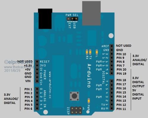
www.elproducts.com |
||||
| McLaren Newbie Joined: 28/06/2011 Location: United StatesPosts: 11 |
Hi Don (and gang), Would the $50 Diligent Max32 board be a good choice for Arduino compatibility? It uses the 100 pin version of the 32MX795' and it already has Arduino shield headers. Would it be possible to add the video, keyboard, and SD card circuitry and connectors to the mcu while avoiding pins going to the 'standard' (original) 20 pin Arduino headers? I suspect it might involve modifying Maximite firmware, but, just wanted to throw out another idea for everyone to chew on. I guess I'm thinking of it in terms of a really nice general purpose board with a Maximite shield (ugh, I hate that cutesy term) with video, keyboard, SD card circuitry, along with the ability to stack other Arduino compatible shields. Cheerful regards, Mike Mike McLaren, K8LH |
||||
| donmck Guru Joined: 09/06/2011 Location: AustraliaPosts: 1310 |
That was one of the boards I looked at Mike, but I got lost in the sea of PIC32 signals, and additional headers. I also dropped the following message on "comp.arch.embedded" news group: [code] Interested in interfacing the PIC32MX695F512H-80I/PT to the Arduino shields. Can someone point me at some existing schematics? [/code] Haven't got a response yet, but it has only been posted 9 hours. But I'll get to Chuck's table in an hour or two. I would appreciate any feed back from anyone at this point, as it may be crunch time on the bus signals. We have that crazy suck...... err, I mean....... volunteer that I was looking for. Cheers Don... https://www.32v8.com/1 |
||||
| donmck Guru Joined: 09/06/2011 Location: AustraliaPosts: 1310 |
Thank you very much Chuck. You are a brave man, and I hope the users will thank you for it, rather than curse you, as the years roll on. I can see users looking at Arduino Shield specs to see how they line up with this pin out, and the Maximite ports driven by MM Basic. What I will do, is give it say 48 hours, just to let the dust settle. And if any man, woman, or child, can show any reason why this marriage would not be lawful, now is the time to declare it. Before we put the ring on the finger, you have that 48 hours to contest this marriage or ask intimate questions. Hey, hold the phone, time out, I have a question. VIN: Would/could this be 9-12VDC? [code] My DonDuino Baseboard Adapter is looking very simple now. DD is just an adapter system from the Maximite I/O bus, to the Arduino Shield Bus, and back to the Maximite Bus signal names, or a bus stacker-adapter system for the Maximite. [/code] The next general question is: Do we now run with Arduino pin outs and pin names for all of our I/O, and organize routines in basic to map out new port bytes? And I'll answer my own question: NO, in fact a great big fat NO, as Marcel Marceau said in the "Silent Movie". The Arduino Shield Bus is only a means of getting from A to B on a stacker structure. If users want to take advantage of Arduino Shields fine. But I think we will loose our identity, if we don't stick with the I/O ports, and pin names that Geoff has already mapped out. I'll rest my case, and if you don't like it, I'll take my case to a higher court. Cheers Don... https://www.32v8.com/1 |
||||
| elproducts Senior Member Joined: 19/06/2011 Location: United StatesPosts: 282 |
Already a flaw in my offer. You are correct in that I was thinking VIN was the 9-12v power from the Maximite but I missed the fact that doesn't exist on the Maximite I/O header so that pin would be Not Used also on the DonDuino Maximite to Arduino shield adapter. I had no intentions of implying the pin names should change. Maximite pin names/number would be the control in software. www.elproducts.com |
||||
| donmck Guru Joined: 09/06/2011 Location: AustraliaPosts: 1310 |
Hi Chuck, I loved your offer. As I said, you are the brave one. :-) What I meant really with VIN, was if we made up an external 9-12VDC available on a plug pack or similar, is that VIN would cater for that input on the Arduino board by having on board regulators for 5 and 3.3V. To put it another way, If we feed the Arduino bus with 9-12VDC, then each individual shield would either cater for it, or ignore it, as it will pick up from the alternative signals 5V and 3,3V if it wants them. In this case this would be the Maximite. If you were running a 5V relay board, VIN might feed an on-board regulator, so that there are no big power drains on the Maximite regulators, which could shut down, or burn up the Maximite box. If we were to supply a DC input point on the DonDuino Adapter for instance, this would run up the stack and be available if required on all boards. Is that getting close? No interpretation of implying this from you on the signals names, on my behalf at all Chuck. I didn't read it this way at all. None, zilch, zero. What I wanted to do was point out to users that it would be a disadvantage to go and rename every thing to Arduino standards, because of the foot print used to stack the boards. The I/O pin out names must be in line with MM-Basic. Cheers Don... https://www.32v8.com/1 |
||||
