
|
|
Forum Index : Other Stuff : Home Built CNC Project
| Author | Message | ||||
Prime_8 Regular Member Joined: 07/12/2014 Location: CanadaPosts: 51 |
looks cool. buts 200$ takes it off my table . LOL Old coder, and bodger of things that may spark. |
||||
Bryan1 Guru Joined: 22/02/2006 Location: AustraliaPosts: 1458 |
Yea I had a look at it and for $250 US seems a tad rich for hobby work and with it saying it needs 2 gig of ram and 64 bit to work thats out of my ball game. |
||||
| Prime_8 Regular Member Joined: 07/12/2014 Location: CanadaPosts: 51 |
i have a feeling i may just fart about with making my own CAM . in 2.5D mode it should not be too hard to make a waterline and then scan line passes. but that is where i leverage what is my time making code worth vs just using linuxCNC or such on one of my old XP rigs. (re-purpose one with a dual boot ) . there seem to be quite a few nice ones , i even found a free cad cam , but what they wanted for registering a free lic was a bit too extensive IMO. ~ DesignSpark Mechanical ~ i could see if you used thier other stuff for making whole device board sand such . Old coder, and bodger of things that may spark. |
||||
powerednut Senior Member Joined: 09/12/2009 Location: AustraliaPosts: 221 |
well, heekscad / heekscam might be a starting point. used to be a free open source product, but I'm not sure if it still is. |
||||
| Bryan1 Guru Joined: 22/02/2006 Location: AustraliaPosts: 1458 |
Heeks cam is open source but for the stable version one the maker does ask for a 20 pound (pommie currency) fee. The only limitation is one needs to remove some code and a browser window popsup with the page to buy the product. I do intend to use that 2.4gig off line for now as I will have either buy a wifi card for the puter or run an ethernet cable to my new work room in the new shed I'm making. That will be some time away as I'm still concreting the main part of the shed which so my wife can setup a studio. (which takes priority if one want to keep living). I do have Mach3 here to use and for linux I will have to find another IDE hard drive to put the ubuntu/emc2 OS on and I already have the disk for that OS here ready to go. Recently I got Sprint Layout 6 so first I need to see if will run on a 32 bit puter and start milling pcb boards as the first project for the cnc. Applying for jobs left right and centre but it is starting to look like once one turns 50 one is on the work scrapheap but still getting a few contracts with gearbox repairs here and there. Looks like a good year with batteries which will not only pay the bills but provide some play $$$ for my projects. Prime if you do want to goahead and have a go at designing a 2.5D system you have one test dummy here...... Cheers Bryan |
||||
| Prime_8 Regular Member Joined: 07/12/2014 Location: CanadaPosts: 51 |
I'm just that type of nut . lol . i would love to figure out a way to cut nice 3D lines . i have figured out a safe way to cut in 2.5D with a bit more automation . usually in 2.5D you set tool height and then start passing XY points. your rig smoothly moves through the XY points. Rite now if you send Z value to my mini mill , it will do any Z value first before moving along to the new XY . what I need to sort is the Z axis delta vs XY . and like how i decide how many steps to feed XY per each motion along a line , i need to figure Z's place . so if delta Z is + , it Must be done before any XY change , and if dleta Z is - , well it must be done after each XY step set. I just have to sort that into my firmware now and then my firmware will support 3D linear moves. I have a spot of contract code to do before I can fart about with the PC side. but I should be able to support CAM from .obj ( and any static game mesh format ) by moving a virtual tool head over the mesh . I would just change up the code i used to place the tires of the truck , and use a tool shaped mesh for the collision test against a target ( stock & parts ). Old video of my depth testing code in action. I have to think if i replace the ground with intended shape and work surface a stock definition , replace a tire with a tool I could virtually pass the tool about the work area. :: pycam looks great except 1 thing ... the compute time even on my quad core W7 rig is measured in hours for simple shapes ?!! im trying to use the HeeksCad i DL from git hub . i need to figure out the interface. if i had cash i would use MeshCAM but lacking $$ and being a crazy build it myself type, ill prolly end up making something that uses 3d engine and collision detection to move a virtual tool around a mesh . Just have not figure out how i will do that just yet . I know i can surface pick against a mesh in code. the nicer CAM packages have advanced tool path options for max speed and low tool stress . I suppose i could use EMC2 live disk . seems some fella made a linux cnc that runs from a live disk ( usb / cdrom ) . Old coder, and bodger of things that may spark. |
||||
| Prime_8 Regular Member Joined: 07/12/2014 Location: CanadaPosts: 51 |
hmm , i just watched this YT vid http://youtu.be/ZxluRPKOUfA never thought to check for a blender plugin . Now i have a reason to finally learn blender. i will have to see if it works with the blender i use now for texture making (game work ) from what I see it does exactly what I was planning on doing but way better ! . Old coder, and bodger of things that may spark. |
||||
| powerednut Senior Member Joined: 09/12/2009 Location: AustraliaPosts: 221 |
I came across this program today which may be of interest: http://www.scorchworks.com/Fengrave/fengrave.html Free txt to g-code program for engraving. Looks like it also does image to g-code. If you don't mind using somebody else's library with your code, there is opencamlib here: http://www.anderswallin.net/cam/ |
||||
| Bryan1 Guru Joined: 22/02/2006 Location: AustraliaPosts: 1458 |
G'day Guy's, Well I did have to go back to find this thread and as I have said I bought a desktop computer from Cashies with win10 on it which was buggy as hell so I put my old Win7 home premium disk in and installed that and some of that fun is shown in my win10 thread. Anyway getting closer as I have bought 3 off DM559 micro steppers and a USB controller board. Here's a pic of the new board setup 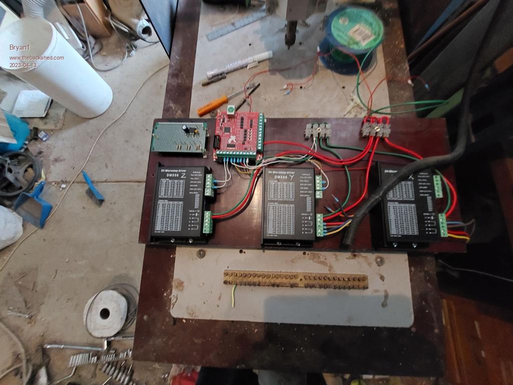 Now on reading the DM556 datasheet one does need to put a 2K resistor on the P and D lines to reduce the current if 12 or 24 volts are used. Now as the schematic for that USB board does have a 10 volt input and in the drawing it shows 12 volts to that pin so with that old simmstick proto board I put a 7812 reg on and so far 3 off !k resistor in series to get 2K as going thru the Adelaide hills all the electronics shops had closed that I used to go to. So went into Home of 12 volt and grabbed a 300 pack of resistors for $10  typically 2K wasn't in there so 2 off 1K's will do the job. typically 2K wasn't in there so 2 off 1K's will do the job.Now in my gear like I found those 50 amp current sensors only to find they are no longer made I new I still had some 7812 chips left. Well the only ones i found was in a DPAK form smd and found it was easy to solder them to the proto board. There is a 100uf 50 volt cap on the input and a 10uf tantalum cap on the output. I will put more earth pins on there to cater for the limit switch's etc. So getting there and soon I do hope to get this running, I do have a mate coming down this weekend to have a look as when connecting something after close to 10 years a second is better than one. Cheers Bryan |
||||
| Bryan1 Guru Joined: 22/02/2006 Location: AustraliaPosts: 1458 |
G'Day Guy's, Well that PCI card turned up while I was away at work last week so today was time for some fun to see if I could get it working I setup my cnc the old way and the old controller board was just how it was left turning on nicely. So fired up Mach3 only to find it hang totally where only a extension cord reset would work  Well on booting up again wifi was totally lost so no net and the computer just hung again so decided that was it.  time to give LinuxCNC a go. time to give LinuxCNC a go. On the install it couldn't find the wifi so did a minimal install as it couldn't connect to the net. This pci card did come with a disk and driver for linux so gave that a go only to find it failed due to the destination folder not existing. So had a play in the terminal making the new folders when Rodger rocked up so that was the end of the days play as the mossies were trying to carry me away. As this distro is a minimal build it will take time to upgrade it but once I get this driver installed I reckon the cnc will become live again. Cheers Bryan |
||||
| Bryan1 Guru Joined: 22/02/2006 Location: AustraliaPosts: 1458 |
G'Day Guy's, Well had a go this morning and YES I did get the F3 screen lit up so tested one of the axis only to find the board was like hammering and no step movement. Now the E-Stop I have setup on the CNC does show on the linuxCNC screen as off so there is a connection thru the PCI card. Yesterday where I had to use my mobile in usb tethering mode just to get the net wasn't needed as the ethernet cable going to my shed wifi router just worked Also made those 2 folders for the starex driver only to find the command failed due to no rule in the folder Got a few jobs to do on the farm so more play later in the day Cheers Bryan |
||||
| rogerdw Guru Joined: 22/10/2019 Location: AustraliaPosts: 905 |
Pleased to see you're making progress Bryan. Might be slow, but it is forward. And thanks for the tour and the bits and pieces yesterday, very interesting to see what others are up to. I enjoyed the wildlife on the way in and out too ... a whole heap of roos just chilling near your gate.  Cheers, Roger |
||||
| Bryan1 Guru Joined: 22/02/2006 Location: AustraliaPosts: 1458 |
G'day Guy's, Well time for a update and that linuxcnc was a total failure  so this cnc has sat as a table ever since. so this cnc has sat as a table ever since.  Now the more I think about this you guy's can always say " sorry no bananas with this one " but I do think and the more I think a CMM2 will get this cnc back to life. Now as I have those 3 DM556 boards all I need to make is a board so opto outputs from the CMM2 to the modules are protected. Got plenty of opto parts on boards here and with some veroboard the protoboard can be made. The more I think about this is eh we need a pulse for enable, a pulse for forward backward and measurable PWM for the motion. Take this with all 3 axis and only 9 pins are needed for the drive, now for the limits one can either just use one pin but as we have a 40 pin connector each limit can be detected. I will need to get a USB power supply for the CMM2 as at the moment I'm using my torch which has a 1.5amp outlet. I got a 19" screen to work but that 24" lcd with all the usb outputs wouldn't work with the CM2. Over the next few days I'll have a go at making a program but coding has always been my problem and the I think about this it time for an old dog to learn new things. Cheers Bryan |
||||
| Bryan1 Guru Joined: 22/02/2006 Location: AustraliaPosts: 1458 |
G'Day Guy's, I have been reading the datasheet on the DM556 and it will accept as low as 5 volts as the logic level and it does go all the way upto 24 volts. I reckon it would be best to use an opto going to a NPN transistor and pulling up the logic lines to 5 volts then using the digital output pins to switch the logic for the enable and direction pins. For the pulse pins PWM so the speed can be adjusted also hooked upto a count pin so the CMM2 can know when the distance is reached. Now I do think to read the G-code if the file was set to a text file each line could be decoded one at a time. Going the opto route is the safest and best way but I'm asking just to see if will work hooking the pins straight upto the DM556 and see if the steppers actually move or just wait and build the opto board first. Cheers Bryan Edited 2023-12-30 17:36 by Bryan1 |
||||
| Bryan1 Guru Joined: 22/02/2006 Location: AustraliaPosts: 1458 |
Well guy's there really is only one way to learn so with the last day of my holidays the 19" monitor, the CMM2 and my torch to power the CMM2 are headed upto the shed to see if I can get these stepper motors going. I tried to get MMEdit going on this new linux setup but no go on setting it up to work on the desktop as this distro was doing the win$ucks thing saying the file wasn't trusted. So I'll be armed with the user manual and programming manual on my laptop and wire up the CMM2 to the DM556 boards and use the ground from the CMM2 for the and just see if I can get this old router back to life then that can of worms will open up If I get some movement I'm going be up to welcome the new year trying to get my code working and the CMM2-CNC will be alive. As I am going back to work on the night of new years day to setup Menz for the new year ahead and eh we all like those choccy's so I have to keep the place going on night shift. Eh for a 59 year old guy to go from a low from nothing to a 148K job one can say I'm enthused to say the least. Where that esteemed forum member Murphy said just kick the can down the road when all else has failed I can see where this CMM2 will route a circuit board in time. Now if I can get some movement I'll put in a dial indicator to count the steps needed to go 1mm then use that count for the COUNT pin. Now for the pulse pin a ramp up ramp down routine will be needed so when we get to a tool it's all set. I am thinking of making a probe with 2 micro switches for reading a part so when the first micro switch is closed the pwm is slowed when the second micro is closed the Z axis is raised so we can read what ever is put under it. Yes I am thinking ahead but eh how do projects get started. Cheers Bryan |
||||
| Bryan1 Guru Joined: 22/02/2006 Location: AustraliaPosts: 1458 |
Ok finally got the CMM2 setup at the shed so in for some fun tonight and plenty of learning. Now a bit of fun to start ran the CMM2 off my laptop and got a SDCard error so came down and got my torch and found that error had gone So just using the usb on the laptop to charge the torch So now I'm setting the main page with Rbox's then learn how to put the numbers in there. etc Aint got the net as my laptop is playing games with the repeater anyway got the programming and user manual pdf's so a bit of fun tonight. Cheers Bryan |
||||
| Bryan1 Guru Joined: 22/02/2006 Location: AustraliaPosts: 1458 |
Well saw the new year in trying to get the steppers to move with no luck, first tried PWM and when I hit run there was a noise coming from from the DM556 but no movement. So the tried servo with the same result. The green LED was on with all 3 of the DM556's so and no red LED lit at all thru the night.Now for reference I did pullup each data line with the 5 volt rail on the CMM2 and connected ground from the CMM2 to the board. Then just tried pin(12) = 1 pause pin(12) = 0 Now using my fluke 865 on scope mode only saw 3.5 volts and no hertz, toggled the direction and enable and did see the voltages change so that did prove the CMM2 does have life outside. So I do think the voltage is too low to drive the DM556 direct and I will need to make up a board and use a higher DC voltage so when the PWM running the 1/2 average voltage is above 5 volts. Anyway my scope should be here later in the week then I can have a real time look at what really is going on. Cheers Bryan Edited 2024-01-01 11:13 by Bryan1 |
||||
| Bryan1 Guru Joined: 22/02/2006 Location: AustraliaPosts: 1458 |
Cool that CRO turned up today and had a bit of fun trimming that supplied probe to get the square wave nice and clean. Anyway after a short sleep in the morning time to setup the CMM2 again and have a look at the signals. That package from element 14 is due tomorrow so it will be nice getting both channels working. Cheers Bryan |
||||
| Bryan1 Guru Joined: 22/02/2006 Location: AustraliaPosts: 1458 |
Well while trying to sleep this morning my phone kept beeping  but eh that package with the probes and fet driver chips did arrive so got to dial in both probes but as far hooking up the CMM2 forgot to bring up the torch. but eh that package with the probes and fet driver chips did arrive so got to dial in both probes but as far hooking up the CMM2 forgot to bring up the torch.Now my thoughts are just setup an interrupt so the pulses and use a function called F so it can be read by the G-code file for feed. So I do need to count the interrupt for distance to find just how many are needed to move 1mm. Tomorrow I will hook up the CRO to look at the signals and I reckon I have to increase the pullup voltage so no more direct hookup I do think as pulling down a 15 volt pullup the output pins from the CMM2 maybe damaged. There are 13 opto's on my old controller so I can use them and use a BC337 on each line to control the signal. That way the CMM2 is isolated and I do have plenty of proto board here. Now I have just spent a week at work and left my USB dongle at home so it will be in my bag come Sunday night so inbetween breakdowns I can be reading and learning on how to code. So if the CMM2 can open a file to read by changing a cnc file to text one should be able to read the first character which will be X,Y,Z,F,S then the number after to execute the command. So a big week ahead to learn but this weekend time does need to be spent getting those MPPT trackers working and making the clamps to hold the panels down. Cheers Bryan |
||||
| Bryan1 Guru Joined: 22/02/2006 Location: AustraliaPosts: 1458 |
OK so for beer only 5 for $25 longncks so time to rug up and go see if I can get some signals from the CMM2 to these DM556 boards. I will decant a bottle of my Barely/Rye whisky I made and just see if I can get some screen grabs and by taking my phone as a USB hub I have net so expect some scren grabs if I can work it out. Cheers Bryan |
||||
| The Back Shed's forum code is written, and hosted, in Australia. | © JAQ Software 2025 |
