
|
|
Forum Index : Microcontroller and PC projects : (MM) wild temp sensor readings
| Author | Message | ||||
centrex Guru Joined: 13/11/2011 Location: AustraliaPosts: 320 |
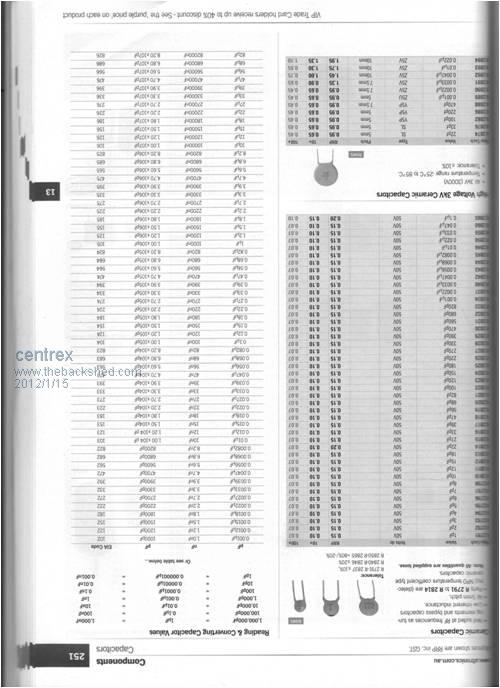
Hi Pete I hope this has come out ok, It is all about how to read Caps I would try either a .01 or a .001 disc ceramic at the input pin. I would also try a sensor on a very short lead well away from other electrical equipment to see if the problem persists. Regards Cliff Cliff |
||||
TassyJim Guru Joined: 07/08/2011 Location: AustraliaPosts: 5898 |
This might be easier to read: http://www.jaycar.com.au/images_uploaded/rescode.pdf 0.001 would be 0.001 uF or 1000pF They can also be marked 102 which is 10 plus 2 zeros. The usual practice used to be put 0.1uF bypass capacitors across the power rails at every IC and a few more to be sure to reduce switching noise on the supply. I am a bit out of date with whats the best type available nowadays. I still have plenty of ceramic and monolithic so they get used a lot. Jim VK7JH MMedit MMBasic Help |
||||
jwettroth Regular Member Joined: 02/08/2011 Location: United StatesPosts: 70 |
Please ignore my previous forum note in this thread that I was getting poor ADC results. I was using some new hardware and wasn't inputting the signal on the pins that I thought I was. The ADC works as expected- sorry for any confusion. I'm working on a way to improve the ADC long term accuracy. I want to use it on my lab bench and found that it varies a bit with temperature. Any ADC is only as good as its voltage reference. The reference for the MM is a filtered version of the 3.3v rail (on the SM1). The LM1117-3.3 regulator that is used puts out between 3.267v and 3.333v at room temp and a constant 10 mA load. This is quite good for a regulator at +-1%. As the regulator is loaded and the temperature varies, this voltage varies basically +-2%. I'm going to verify this in some tests but this is what the data sheet for the regulator would lead you to believe. (ref data sheet - http://www.ti.com/lit/ds/symlink/lm1117-n.pdf) If the MM is nominally at room temperature and your temp sensors are remote, the variations are likely very small and can probably be ignored. I'll verify this. I'm now doing some tests where I've connected a high stability voltage reference to Channel 1 of the MM and am making readings at varying temperatures. The reference is 2.500v +-.05% (Analog Devices REF-43 from my junkbox). I don't want to modify the hardware of my SM1- I just read the reference channel and can make real time corrections to my readings on other channels. I'll let you know what I learn, I think this could make the MM ADC more stable long term. Voltage reference chips are available and inexpensive at these tolerances. Regards, John Wettroth |
||||
pcaffalldavis Senior Member Joined: 17/10/2011 Location: United StatesPosts: 187 |
This is interesting and brings up another subject. The MM for the wood fired boiler will be located at the boiler, not in the house. It will be inside an insulated door on the boiler, beneath an insulated exterior metal skin. The boiler itself will be insulated with 2" of styrofoam sheeting all around and the boiler control panel with electronics and relays will be outside the foam but beneath an insulated door. So I'm thinking the MM will experience temperature ranges of perhaps 10 to 50 degrees C. I wonder if this will significantly affect sensor readings? I've ordered up a nice collection of disc capacitors so in a few weeks I can add these to all four of the temperature sensor circuits. Since I don't have four the same right now I'll wait until the collection arrives from China to do these modifications. I will put a voltage divider on each as well using two additional resistors as was suggested. This would have been necessary to get the full range of the LM335 for the sensor in the boiler water anyway since it will get up close to 90 C. Thank you everyone for your help and patience. I'll report back in a few weeks when all the modifacations have been completed. Pete in Hyder We're all here 'cause we're not all there. |
||||
| centrex Guru Joined: 13/11/2011 Location: AustraliaPosts: 320 |
Something else you could try to get rid of garbage on the sensor wires is to thread the cable through a ferrite toroid a couple of times. If you have an old crt monitor laying about these usually have a ferrite toroid on the signal cable just cut it off and thread the wire through it at least twice Cliff Fitted as close to the computer as possible. Cliff |
||||
