
|
|
Forum Index : Microcontroller and PC projects : ColorMax Pre-order
| Author | Message | ||||
johnbig Newbie Joined: 23/06/2011 Location: AustraliaPosts: 21 |
Hi CircuitGizmo, The ColorMax arrived 2 hours after the previous message!!! Thanks for the quick reply Kind Regards John Leate |
||||
| paceman Guru Joined: 07/10/2011 Location: AustraliaPosts: 1329 |
Hi CG, That's done the trick! I removed R6 and replaced it with a 1/4 watt through-hole 120K - didn't have an 0603. R6 was a 1K as you said. Both 9v & 12v IN give 5.0v & 3.3v where they should and USB IN is fine still, 4.8v (from my notebook) and 3.3v. All inputs now fire up the RTC on power-up. I cut the leads of the through-hole back to about 5mm each end and bent them to connect from the R6 switching chip side (going to pin12 "enable"), back to the Vin side of the "big" capacitor rather than try to go to the other R6 pad. Tricky, but not too bad with the help of my trusty stereo microscope, de-solder braid and some flux gel! Many thanks for the solution. Greg |
||||
centrex Guru Joined: 13/11/2011 Location: AustraliaPosts: 320 |
Hi all especially CG My Colour Maximite turned up today. Fired it up with 9volts no joy withe RTC and it had the shimmers. Loaded 4.1 the shimmers have gone but still no RTC. Tried again with supply from the USB all ok then tried with 12 volts all ok incl the RTC. Now to find the pesky resistor and try to steady the shakes to do some fine soldering or just leave it on 12V. Regards Centrex Cliff |
||||
| centrex Guru Joined: 13/11/2011 Location: AustraliaPosts: 320 |
I have just had a look at r6 on my board it appears to be labelled the same as r24 which is above r6 with my simple magnifying glass it appears to have 018 embossed on it. Can one just cut the track leading away from r6 and insert a 120k resistor in series leaving r6 in place. I would have more hope of doing this than trying to change r6. Cliff Cliff |
||||
| paceman Guru Joined: 07/10/2011 Location: AustraliaPosts: 1329 |
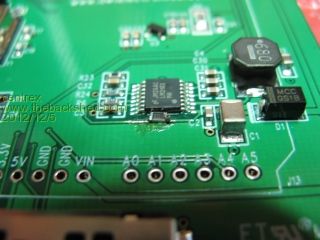
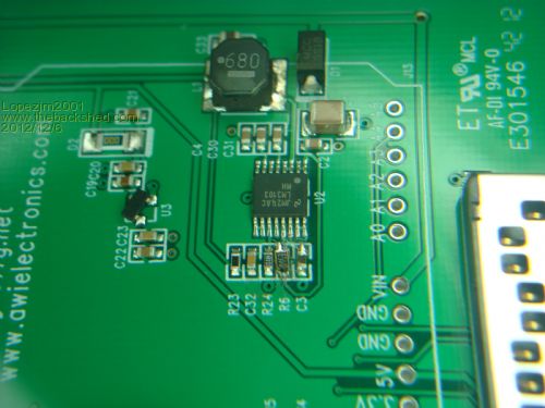
Cliff, Here's a (bad) photo of the through hole R6 resistor I put in after removing the SMD. I think you'd find this method easier than trying to cut that tiny track and solder one there. One end of my mod is terminated at C1 (the other end of that same track) rather than on the SMD pad and the other end of course goes to the SMD pad connected to pin 12 of the switching chip. If you don't have a good magnifier and lighting it'll be pretty difficult so I think it'd be better to wait for CG's comments before tackling it. You can still run it all properly from USB or a 12v supply. 
Greg |
||||
CircuitGizmos Guru Joined: 08/09/2011 Location: United StatesPosts: 1421 |
Greg's approach is an excellent solution. It is certainly easier to solder to other locations on the same net/track - a larger place to solder to. Here are a couple of pics that will help: 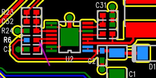
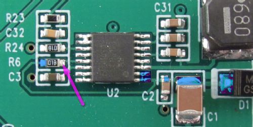
Carefully remove R6. One side of the replacement resistor (120 kohm) must connect to the pad that the purple/violet arrows is pointing to on both pictures. The other side of the replacement resistor should connect to one of the pads highlighted in blue. Micromites and Maximites! - Beginning Maximite |
||||
donmck Guru Joined: 09/06/2011 Location: AustraliaPosts: 1310 |
Even I can understand that Rob. 
Nicely drawn and explained. With the Red track that cuts through the text U2, the tracking is easily seen to these 6 potential Blue points. Don... https://www.32v8.com/d |
||||
bigmik Guru Joined: 20/06/2011 Location: AustraliaPosts: 2870 |
Cliff, All, The above intrigued me as that marking didnt seem to fit my understanding of SMD resistor markings. So I looked it up and I think it would actually be 01B which is a new way of marking 1% SMD Resistors. 01=100 B=x10 Value =100x10 =1000 =1k which is what Rob said they used instead of 120k By the above code it should have a 120k device marked as 08D (118k) or 09D (121k) See the following link for further information SMD Resistor Markings Regards, Mick Mick's uMite Stuff can be found >>> HERE (Kindly hosted by Dontronics) <<< |
||||
| CircuitGizmos Guru Joined: 08/09/2011 Location: United StatesPosts: 1421 |
It is a B and that is a nice page that you linked to! Micromites and Maximites! - Beginning Maximite |
||||
| bigmik Guru Joined: 20/06/2011 Location: AustraliaPosts: 2870 |
Thanks Rob, I really like his one line comment right at the end "Personally, I'd check with an ohm-meter!" Regards, Mick Mick's uMite Stuff can be found >>> HERE (Kindly hosted by Dontronics) <<< |
||||
| paceman Guru Joined: 07/10/2011 Location: AustraliaPosts: 1329 |
Here's some points that might help if you're going to tackle this. Removing R6 is probably the trickiest part. I had some 0.025 inch solder wick available and that's about the right size - cut off square any old, used stuff. If you have to use wider wick be very careful you don't de-solder the adjoining resistors or IC pin - you might be able to cut it at an angle to help. My soldering iron tip is a wedge shaped one a bit more than 1 mm wide and that works OK but finer would probably be better. Keep the iron on the wick as you pull the wick away - you don't want the wick soldered to the pad! Make sure the iron's tip is properly silvered and wipe it well (folded up kitchen paper works well) immediately before you do it. I also put a tiny dab of flux gel on the pads (literally from the point of a pin) first and it all came off well - how much the flux helped I'm not sure. I was watching the solder "wicking" up through the stereo microscope which certainly helps. Give the resistor a little push with the iron back on the pad after you've done the wicking to free it - don't lose it! 
If you're using a through-hole 120K replacement, cut the leads to about 6mm from both ends of the resistor and take some time to bend them to exactly fit the length between the R6 pad IC pin12 side and the other termination at the C1 resistor - I think that's by far the easiest place to solder the other end. Pre-tin each end of the resistor wire. Solder the C1 end first then you can easily  re-position the other end against the tiny R6 solder pad before you solder it. Again clean the iron's tip immediately before soldering each end and also this time melt a tiny bit of resin-cored solder onto the clean tip before soldering. Another tiny dab of flux on each pad end before soldering it is a major help. re-position the other end against the tiny R6 solder pad before you solder it. Again clean the iron's tip immediately before soldering each end and also this time melt a tiny bit of resin-cored solder onto the clean tip before soldering. Another tiny dab of flux on each pad end before soldering it is a major help.
Good luck, Greg |
||||
| hitsware Guru Joined: 23/11/2012 Location: United StatesPosts: 535 |
Gulp ! :) I think I'll stick with a 12V wallwart ..... |
||||
| bigmik Guru Joined: 20/06/2011 Location: AustraliaPosts: 2870 |
Dont fear about removing the SMD resistor.. just add more solder to both sides (excess solder so it blobs) then using your iron melt both sides, turn the tip so it rests on the top of the SMD it will melt both sides at the same time, then quickly push the SMD and it will move away... Then clean with solder wick and you are ready to fit an new one.. The Blobs will keep the joint from cooling too quickly. I am sure there will be people locally who can and will do it for you... I am happy to assist if anyone wants me too. Regards, Mick Mick's uMite Stuff can be found >>> HERE (Kindly hosted by Dontronics) <<< |
||||
| paceman Guru Joined: 07/10/2011 Location: AustraliaPosts: 1329 |
That sounds a lot easier than my method Mick - an old hand versus an amateur! Greg |
||||
| centrex Guru Joined: 13/11/2011 Location: AustraliaPosts: 320 |
All good info. I have a 100k and a 150k smd resistors if the thing works with a 1K resistor it cannot be to critical. I dont have anything less than a 1/2w thru hole resistor, I will give it some more thought. Cliff Cliff |
||||
| centrex Guru Joined: 13/11/2011 Location: AustraliaPosts: 320 |
Decided to bight the bullet and cut the track and soldered in the 100K resistor not the neatest job but it all now works on 9 volt input. The hands shake a bit after 75 years. Anyway I am happy, now to put the colormite to a good use. Thank you all. Cliff Cliff |
||||
| paceman Guru Joined: 07/10/2011 Location: AustraliaPosts: 1329 |
Nice going Cliff - that's two options now. What size SMD is that, an 0805 or 1206? Greg |
||||
| hitsware Guru Joined: 23/11/2012 Location: United StatesPosts: 535 |
Thanks, but mine is working fine for my purposes. I wouldn't have known of the problem had it not been mentioned here ...... |
||||
| Lopezjm2001 Regular Member Joined: 08/07/2012 Location: AustraliaPosts: 42 |
I received my Colourmax today in the post. Now to read previous post so find out why someone would want to modify their PCB. Thanks Gizmos. Lopez |
||||
| Lopezjm2001 Regular Member Joined: 08/07/2012 Location: AustraliaPosts: 42 |
I managed to salvage a 115K SMD replacement resistor from a faulty Enginer BMS16D. 115K was the nearest value I could find. Note the great workmanship displayed in the photo, oh yes, this is definitely the Gizmo flag ship. I did the job with a fine tip temperature adjustable (300degC.) soldering iron and a magnifying lamp. (I was referring to the workmaship of the photo itself). EDITED: Now it will only boot up on occasions on my computer monitor at work using a 12 Vdc supply. The VGA monitor would not work at all when the Coulourmax was powered by the USB plug. I think I should have left it unmodified. But on the plus side the RTC works OK. I think it was booting up OK just the VGA monitor sometimes works and sometimes does not only when using a 12Vdc supply. Just got home and it boots up every single time using my laptop and a 7" VGA screen using a USB plug. I also set the jumper setting when going to and from USB and 12Vdc supply every time. It also works perfectly using a 12Vdc power supply. It seems the Colourmax has an issue with my VGA monitor at work. Lopez |
||||
