
|
|
Forum Index : Microcontroller and PC projects : Growing a Maximite
| Author | Message | ||||
| paceman Guru Joined: 07/10/2011 Location: AustraliaPosts: 1328 |
Ahhh.. the penny drops! I hadn't thought of anyone needing to do it by method 2 so I was wondering about that myself. Another thing that's not clear to me is the cable. MicroChip sell the PicKit3 (they call it the PicKit3 In-circuit de-bugger) with a standard USB A to mini A lead which no doubt is for the PC/PicKit connection. The other end has the two row 12 pin female connector which presumably I have to make up a cable for to connect to the ICSP pins of the break-out boards I have PIC32 break-out. Again presumably another cable is needed with an RJ45 connector if you want to program the smaller DIP PICs because they seem to make a big thing about their "standard" RJ45 connector. Is it just that they use the RJ45 connector on their programming boards - if so, what do other generic programming boards normally use? Is their any reason I can't use a solderless proto board to hold and program the PICs if I just connect the appropriate ICSP signal and power leads to it? If all the above is OK why don't MicroChip supply an ICSP/ &/or RJ45 cable with the PicKit? We've all got the USB A / USB micro anyway but not the others which are specific to them. Greg |
||||
Grogster Admin Group Joined: 31/12/2012 Location: New ZealandPosts: 9070 |
F**kin' good idea!!!! 
I had not thought of that either, to paraphrase paceman for a moment... That IS a great idea, and would make firmware updates much easier if you did not have to cart your laptop around too.  Smoke makes things work. When the smoke gets out, it stops! |
||||
| MOBI Guru Joined: 02/12/2012 Location: AustraliaPosts: 819 |
PROGRAMMING A PIC USING ICSP OK, here goes. A pic is often programmed In Circuit - i.e it is left in situ and not removed and placed in a programmer particularly these days as pics tend to be smd and consequently are hard (impossible??) to remove. So, a facility is set up to enable the pic to be programmed in situ. There are pins on every pic that are used (among normal i/o functions) for In Circuit Serial Programming. These can be found in the pic data sheet. Generally there are 5 pins required. 1). Vdd (3.3 or 5vdc - device dependent) 2). VPP (also usually the /mclr (reset) pin) Programming voltage 3). PDD - serial Programming data to/from the PROGRAMMER 4). PGCK - Programming clock from the PROGRAMMER. 5). O volt (gnd) These pins are manipulated by the PROGRAMMER in accordance with data and commands sent to it by the PC software via a serial connection (usb or comm or usb/serial). You can't just send serial data to the target pic as the data input can be of a number of bit lengths which is pic dependent, hence the need for an intermediary "translating" device (PICkit3??) The above refers to 2 wire programming (pgd and pgclk). There is a 4 wire connection called JTAG (Joint Test Action Group) that allows data to be fed back to the PC during normal operation so that programme debugging can be used. I thought the output from PICkit3 was a 6 pin in line socket (I am 400KM away from it at the moment so can't check). You will need to make up your own lead. The reason a generic lead isn't supplied is because of the ICSP method. Access to the programming pins on the target pic could come out anywhere on the board, so it is up to the user to make sure the PICkit signals go to the appropriate place. You can take a 100pin pic32 chip and mount it (not soldered) in a chip carrier that allows you to connect to pins as needed. As long as you apply power to the pic in the appropriate places and hook up the programming signals to the appropriate places, it will all work. No external xtal is needed as there is a high speed oscillator built into the pic to handle programming. Depending on how the pic board is designed, jumpers may need to be removed to allow unimpeded connection of the programming signals to the target pic. Using a RJ45 socket is just a convenient way of connecting the board but not always suitable. I hope all that made sense. David M. |
||||
| Grogster Admin Group Joined: 31/12/2012 Location: New ZealandPosts: 9070 |
I am guessing this is how SC pre-program the chips they sell on their website, as these are just the chip, but have not been soldered to, nor do they come on any kind of carrier board. Smoke makes things work. When the smoke gets out, it stops! |
||||
djuqa Guru Joined: 23/11/2011 Location: AustraliaPosts: 447 |
. Microchip provides inexpensive production programming Silicon Chip most likely uses that option. It is only $10 USD or less per order plus 50cents (or less) per chip VK4MU MicroController Units |
||||
| Grogster Admin Group Joined: 31/12/2012 Location: New ZealandPosts: 9070 |
Okey dokey. Smoke makes things work. When the smoke gets out, it stops! |
||||
| paceman Guru Joined: 07/10/2011 Location: AustraliaPosts: 1328 |
That informs me a whole lot better than the MicroChip site David - they should get you to write a pre-amble for them! Greg |
||||
| MOBI Guru Joined: 02/12/2012 Location: AustraliaPosts: 819 |
At the risk of sounding defamatory, I have many times been frustrated by Microchip's documentation, often finding the vital bit of imformation in some "fine print" after thought in a remotely related topic. David M. |
||||
| paceman Guru Joined: 07/10/2011 Location: AustraliaPosts: 1328 |
David you're right there, the PICkit3 is a 6 pin in-line connector, not 6 double = 12 as I said.  I just pulled out my PICkit3 from the plastic display wrap to check - when it's in the packing the single in-line is reflected almost perfectly making it look like a double. My mistake - sorry about that. I just pulled out my PICkit3 from the plastic display wrap to check - when it's in the packing the single in-line is reflected almost perfectly making it look like a double. My mistake - sorry about that.
Greg |
||||
| Ray B Senior Member Joined: 16/02/2007 Location: AustraliaPosts: 219 |
MOBI Said "but we did up some artwork on plain paper using a mono Brother laser, exposed and etched a board." MOBI I'm interested that you were able to use the Toner Transfer method with a Brother Laser. From my own experience and also readings on various forums I was under the impression that the Brother Laser Ink (powder) did not seem to have the correct plastic content for transfering using heat to a clean copper board properly. What model is your Brother printer and are you using genuine Brother Cartridge or a replacement cartridge. Regards RayB from Perth WA |
||||
| aargee Senior Member Joined: 21/08/2008 Location: AustraliaPosts: 255 |
Programming the PIC all really easy-peasy. I went through the whole process with the UBW32 in the early days (June '11) before Geoff supported the UBW, to see if the Maximite FW could run on the UBW hardware. Essentially the UBW board is a bare bones PIC32, have a look here . Excuse some of the links to Geoff's page - they don't exist any more! For crying out loud, all I wanted to do was flash this blasted LED. |
||||
| Grogster Admin Group Joined: 31/12/2012 Location: New ZealandPosts: 9070 |
Come to think of it, that's right. I also have a brother laser printer, and I could have heated the board till it delaminated from the fiberglass, and the toner would never transfer to the board. ...then I found out about the Brother toner not having the required plastic content... Smoke makes things work. When the smoke gets out, it stops! |
||||
| MOBI Guru Joined: 02/12/2012 Location: AustraliaPosts: 819 |
Sorry about the confusion. Somewhere along the line (I thought it was in this thread) I mentioned that I used a Brother laser printer and plain paper - I thought I said that we used the Kinsten (Ultra Violet) method of exposing and etching the board. Yes, I found out quite some time ago that the Brother toner will not transfer. Much to my disgust as I have quite a bit of plain double sided PCB from about 25 years ago (still good). Downwind and I rub a bit of clear cooking oil into the back of the artwork to make it more translucent. Works really well and is much cheaper than graphic paper. Works really well with laser toner - ink jet tends to wick between the tracks. Just don't over oil as it is then hard to etch. Just made it home (6 hour drive) from Downwind's so am still catching up with watering etc. David M. |
||||
| MOBI Guru Joined: 02/12/2012 Location: AustraliaPosts: 819 |
I know all this has been done a year or so ago, but I want to see if I can make all the boards and bits in my "back shed". The PIC32 chips arrived from Portugal and I have soldered one on the break out board I made in earlier post this thread. It all looks nicely lined up thanks to a nifty little smd holding tool downwind made for me a couple of years ago. I had used it on 8 pin smd, but this time it was really in its element with the 100 pin PIC32. The headers are fitted, now just have to make up a 3.3v power supply. Everything I have done to date has been 5vdc or higher. So here goes the next step. Still have to make up a programming cable to go from the PICkit3 to the PIC32. 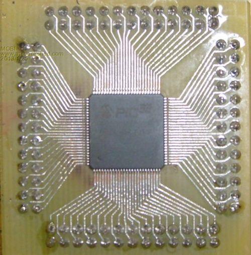
David M. |
||||
| MicroBlocks Guru Joined: 12/05/2012 Location: ThailandPosts: 2209 |
Don't forget the decoupling caps! They need to be as close to the pins as possible. The PIC32 is really sensitive for this especially at higher speeds. It might work if you solder them direct to the pins of the connector (smd's should fit) as most of the ground and vcc pins are next to each other. Microblocks. Build with logic. |
||||
| MOBI Guru Joined: 02/12/2012 Location: AustraliaPosts: 819 |
No, I certainly won't. For years playing with TTL at around 1MHz I only used them when I absolutely had to and got away with it fairly well. However, recently I turned a PIC16F88 into an I2C 7 channel ADC and the system kept randomly locking up on me. Couldn't find any hiccup in the firmware so in desperation put on a 104 decoupler and Voila! problem solved. Thanks for the reminder as I might have got impatient and tried it without the caps, though the PIC32 programming PDF Doc is very pointed about power supply conditioning. Edit: I just had a look at the tiny proto board you were doing with the back plane. I also have been toying with the same idea. How's yours going David M. |
||||
| MicroBlocks Guru Joined: 12/05/2012 Location: ThailandPosts: 2209 |
It is going slow, work and such get in the way. :) I also need to change some things as i would like to have it 100% compatible with the color mm through an add on board. The cpu board itself would then remain generic. The only thing is now to decide what will be on the generic. I can include a mini usb type B and a usb host A type connector, a 3.3v regulator, ICSP of course, a supervisory chip to control the reset state of the PIC32 and leave it at that. I still have to figure out how i can keep the internal RTC of the PIC32 running on battery when power is removed. It is not straightforward to say the least. I can see why Geoff decided to add an extra chip for that functionality. All the maximite specific stuff will then be put on a companion board that can be piggybacked or cabled to the cpu board. The backplane brings out the PMP port an SPI 4 I/O that can be use together with the SPI to enable chips and an I2C to connect a range of stuff. I have schematics and layout available (diptrace) if you want to look and comment on it, shoot me a PM with your email and i can send it to you. It is in its rev B now and not completely 'clean' yet. Microblocks. Build with logic. |
||||
| MOBI Guru Joined: 02/12/2012 Location: AustraliaPosts: 819 |
Years ago, I built a back plane based system rather like the old S100. As all the other boards had to be compatible with whatever processor I plugged in, the only extra hardware I put on the processor board was bus and control buffering and any crystal or other clockling circuitry. e.g, the 6800 needed a 2 phase clock generator, the 6502 only a single phase clock. I would probably go along the same lines if I built a PIC based backplane system. Also, if the backplane traces are too long, they may need to be terminated with an appropriate impedence. My email address should be on my profile. David M. |
||||
| Grogster Admin Group Joined: 31/12/2012 Location: New ZealandPosts: 9070 |
@ MOBI - I am really impressed with your carrier board.  I would have thought that 0.5mm pin spacing was really too fine for home-brew boards, and expected that you really would have to get a professional one like at Futurelec, as your printout or film neg or pos would not be able to get enough accurate resolution to define the tracks without shorting them out. Great work. It has made me re-think if I need to get my MM clone prototype PCB made at a factory, or for the prototype, perhaps I can home-brew mine too. I would have thought that 0.5mm pin spacing was really too fine for home-brew boards, and expected that you really would have to get a professional one like at Futurelec, as your printout or film neg or pos would not be able to get enough accurate resolution to define the tracks without shorting them out. Great work. It has made me re-think if I need to get my MM clone prototype PCB made at a factory, or for the prototype, perhaps I can home-brew mine too.  Also, on the 6502 CPU - what a beast for it's time. That processor was in just about all the popular home computers, including my much loved Atari 8-bit machines,a nd the Commodore 64. Not sure what the Spectrum and TRS80 had in them - perhaps someone(or even yourself) can enlighten me. ZX81 was a Z80 processor from memory... Also, on the 6502 CPU - what a beast for it's time. That processor was in just about all the popular home computers, including my much loved Atari 8-bit machines,a nd the Commodore 64. Not sure what the Spectrum and TRS80 had in them - perhaps someone(or even yourself) can enlighten me. ZX81 was a Z80 processor from memory...
@ everyone - I still play a lot of the old Atari games using the ATARI800 emulator for the PC, and even when I used to play the games on the genuine machine, there is something beautifully perverted about a game on that hardware, still having plenty enough speed to be able to beat you at just about any of the games where the nasties out to get you move faster on the next level, until they do get you. One of my favourite games was DAN STRIKES BACK - I could never beat this one. 
But, I digress - again...
I am surprised by comments that the battery backup for the PIC 100 chip is not straightforward. Does the chip not have a VBAT pin somewhere in those 100 pins? Obviously not, or Geoff - as pointed out - would not have used an external RTC. Smoke makes things work. When the smoke gets out, it stops! |
||||
bigmik Guru Joined: 20/06/2011 Location: AustraliaPosts: 2870 |
Hi Groggy, I can tell you with 100% certainty that the TRS80 had a Z80 CPU (all 1.77 MHZ of it) Regards, Mick PS. I worked on a lot of 6800 and 6808 boards at work back in the `80s. But z80 was my hobby.. Mick Mick's uMite Stuff can be found >>> HERE (Kindly hosted by Dontronics) <<< |
||||
