
|
|
Forum Index : Microcontroller and PC projects : External watchdog chips...
| Page 1 of 4 |
|||||
| Author | Message | ||||
Grogster Admin Group Joined: 31/12/2012 Location: New ZealandPosts: 9975 |
Does anyone know of any good and cheap watchdog timer chips? I was just going to program a PICAXE(a wee 8-pin one should do it) to monitor a PWM signal from the MM, and then reset the MM if it vanishes for more then a few seconds. That's easy enough to do, but perhaps there are special chips I should be looking at for this task? EDIT1: I found this one on Element14: http://nz.element14.com/maxim-integrated-products/max6369ka/ watchdog-timer-selectable-tout/dp/2113164 EDIT2: I found this one, which is only $1.79 - that's hard to beat. http://nz.element14.com/texas-instruments/tps3823-33dbvtg4/s upervisor-watchdog-smd-sot-23/dp/1234637 What do the rest of you use? EDIT3: Link above to the $1.79 unit is not suitable - it is a low-voltage watchdog. I need the pulse monitoring type, so that if the MM code crashes, the external watchdog will reset the MM chip. Still looking around... Smoke makes things work. When the smoke gets out, it stops! |
||||
| MOBI Guru Joined: 02/12/2012 Location: AustraliaPosts: 819 |
I don't think you can go past a 08 picaxe for a watchdog particularly as it can be easily configured to monitor any pin that has regular data on it and not just a specific pin. The only problem I have with using a picaxe is it can also lock up for what ever reason and then you have the blind leading the blind. Having said that, it is not difficult to programme a 8 eg 12F675 pin pic in which case, the internal watchdog timer can be used to at least keep the pic alive using a software wdt reset. David M. |
||||
centrex Guru Joined: 13/11/2011 Location: AustraliaPosts: 320 |
What is wrong with a NE555 as a missing pulse detector. regards Cliff Cliff |
||||
| MOBI Guru Joined: 02/12/2012 Location: AustraliaPosts: 819 |
Nothing - Its quite a good idea. The only drawback is that it needs extra components but they can be SMD to save space. I suppose the drawback of a virgin pic is that it needs programming. David M. |
||||
| Grogster Admin Group Joined: 31/12/2012 Location: New ZealandPosts: 9975 |
@ MOBI: [quote]The only problem I have with using a picaxe is it can also lock up for what ever reason and then you have the blind leading the blind.[/quote] Yeah, that was one of my concerns, but to be fair and give credit where credit is due, I have never had lock-ups with my PICAXE circuits, once I started using the correct decoupling caps etc. This is not to say that this one won't, but to date, they seem rock solid. I always use 100n SMD caps within 1mm of the power pin though, to help keep their juice nice and clean. @ centrex: Never head of using a 555 as a pulse detector. I must have missed that one growing up. I certainly used the 555 a lot as one-shot timers etc. Is this pulse-detector idea in the 555 datasheet? I have the PDF somewhere, I will hunt it out and read it to see if there is anything in there. If you have a link to a circuit, please do post that link here, so I can have a read. Smoke makes things work. When the smoke gets out, it stops! |
||||
| MOBI Guru Joined: 02/12/2012 Location: AustraliaPosts: 819 |
Never used 555s too much, but I didn't think the 555 was "retriggerable" i.e once triggered, subsequent triggers keep it in the ON state. There are cheap 74H series chips that are retriggerable e.g 74H123 (dual mono) selectable pos or neg trigger. Might do the job. Can you programme a 12F675 PIC? David M. |
||||
| Grogster Admin Group Joined: 31/12/2012 Location: New ZealandPosts: 9975 |
No, the only programmer I have is the Picaxe three-wire thing, and it's associated Programming Editor. It would be pretty easy to program a picaxe for the task - I might just have a go on the bench and see what happens...  Smoke makes things work. When the smoke gets out, it stops! |
||||
| centrex Guru Joined: 13/11/2011 Location: AustraliaPosts: 320 |
missing pulse a search of the web will get you heaps. I posted a pointer but it wont work, try the web regards http://technosains.com/MissingPulseDetectorBasedOn555.htm try this. Cliff |
||||
| Grogster Admin Group Joined: 31/12/2012 Location: New ZealandPosts: 9975 |
Thanks for the link, centrex. 
I will read it now. Smoke makes things work. When the smoke gets out, it stops! |
||||
| Grogster Admin Group Joined: 31/12/2012 Location: New ZealandPosts: 9975 |
Hi folks. 
I just need to revive this thread for a few more posts, as I am now playing around with the watchdog reset idea for the MM. I built the 555 missing pulse detector linked to by centrex, and although it works very well indeed, I have found one really major issue with it, so I want to run it past the rest of you for ideas. The problem with this circuit, is that on initial power-up, the 555 output is low, meaning that if connected to the MM, at power up, the 555 circuit will hold the MM reset line low, the PIC32 will never start-up, and the MMBASIC code will not run to be able to start sending pulses to the 555 circuit in the first place. See what I mean? Once I start manually pulsing the input to the 555 circuit, the 555 output goes high as expected, and provided I keep pulsing the input, it stays high. With my experimental R/C combination of 560K/10uF, once I stop pulsing the input, about 6 seconds later, the 555 output goes low. Start pulsing the input again, and the 555 output goes high again and stays that way while I keep pulsing the input. That is all GREAT, and EXACTLY how I wanted it, but the initial power-up problem with this circuit still remains, in that if actually connected to the PIC32, the 555 will pull the PIC32's reset line low, and keep it there until the 555 input starts pulsing. However, as the PIC32 is held in reset like this, it never starts up, the code never runs, so the pulses never start, and the MM stays in a state of electronic limbo forever! 
Does anyone have any ideas on how to stop that? I KNOW I can do this with a PICAXE 08 chip no worries, as you can program the PICAXE to wait for a few seconds at power up BEFORE it starts looking for input pulses. ...but I liked the idea of NOT using an MCU-based watchdog, to eliminate issues with the watchdog leading to the "Blind leading the blind" as mentioned earlier in this thread by MOBI... Come to think of it, this 555 circuit has the exact same problem when it DOES reset a running PIC32, as it holds the PIC32 reset line low when tripped, instead of a pulse on the PIC32 reset line, which is what we really need... I think I will have a play around with the PICAXE method, but I would still love to hear other members' input - it could be a simple enough fix. Smoke makes things work. When the smoke gets out, it stops! |
||||
kiiid Guru Joined: 11/05/2013 Location: United KingdomPosts: 671 |
This is just an idea for you. You can actually build a missing pulse detector in a much easier way. All microcontrollers have Schmitt triggers on their reset input (at least PICs certainly have) and you can use it by adding a simple RC circuit outside. Additionally you don't need to generate the external reset pulse on power up event as it is internally generated by the PIC. See the picture. You drive the 'CHARGE' from an output of the PIC, periodically charging the capacitor, which then slowly discharges itself through a resistor and feeds the '~MCLR' input of the PIC. When the voltage gets under the reset threshold as per the datasheet, the PIC will reset itself. So you have to periodically recharge the capacitor by sending a short pulse to it, to keep the micro from resetting. The values of the resistor and the capacitor can define the maximum reset period. 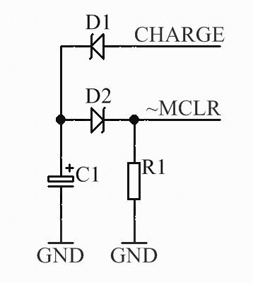
http://rittle.org -------------- |
||||
| Grogster Admin Group Joined: 31/12/2012 Location: New ZealandPosts: 9975 |
An excellent idea and so simple! 
I will try this out, but I think we would still have the same issue, would we not, in that at power-up, the reset(~MCLR) line will be held low by R1 in your diagram, so the PIC never actually starts running. Yes? No? I will set this up on the breadboard and try it out with LED's. Thanks for posting and for the diagram - I will let you know what happens. Smoke makes things work. When the smoke gets out, it stops! |
||||
TassyJim Guru Joined: 07/08/2011 Location: AustraliaPosts: 6538 |
I have plans to use a picaxe. The picaxe will wait for X number of pulses before it starts looking for a missing pulse. That way, it doesn't matter how long your program takes to start. For a pulse, I toggle the power LED. This saves an output and gives a nice visual indication that things are working. Rather than a reset of the Maximite, I will remove all power for a few seconds. This resets a few peripherals as well. I currently do this with the PC that is receiving the Maximite data. No data for X seconds and do a reset. This also means that I can reset the Maximite remotely which has been handy on a previous trip away from home. No problems with the data acquisition so far this trip but one of my cameras is playing up and it happens to be the one that I don't have remote power control for. Jim VK7JH MMedit |
||||
| Grogster Admin Group Joined: 31/12/2012 Location: New ZealandPosts: 9975 |
Keep us posted on your PICAXE version.
I rather like the idea of being able to reset all connected peripherals at the same time as you reset the PIC32, so I might yet move to the PICAXE 08 idea I have been kicking around since the first post.
...still tinkering. Smoke makes things work. When the smoke gets out, it stops! |
||||
| kiiid Guru Joined: 11/05/2013 Location: United KingdomPosts: 671 |
That could be a problem unless R1 is a value high enough (I think there was an internal pull-up on the MCLR input). But that potential issue could be easily solved by adding a pull-up resistor on the 'CHARGE' line (before the diode!). Thus it will provide the initial charging for the capacitor and later on it won't matter because you will be holding the line low by the output unless charging. This one should be fine in all cases. In fact you may not need D2 at all. I put it there only to neutralise the effect of the internal pull-up, but it is very small anyway. With these values it should give you a nice window of about 0.5s to recharge. 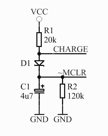
http://rittle.org -------------- |
||||
| MicroBlocks Guru Joined: 12/05/2012 Location: ThailandPosts: 2209 |
You still need to follow these pic programming rules when you want to be able to program the pic. Make sure you can take that capacitor and maybe other parts that interfere out of the circuit by jumpers or switches when it is time to program. 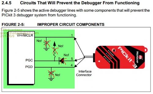
And in case you missed its discussion see here: forum post , Geoff is thinking about adding a WATCHDOG command to MMBasic that uses the internal pic32 watchdog removing the need for extra circuitry. Microblocks. Build with logic. |
||||
| kiiid Guru Joined: 11/05/2013 Location: United KingdomPosts: 671 |
If the capacitor is temporarily disconnected (let say through a jumper), there is absolutely no issues with the programming. Adding an internal watchdog command I think is not 42. I have personally seen microcontrollers stuck so much that the internal watchdog is stuck as well. http://rittle.org -------------- |
||||
| Grogster Admin Group Joined: 31/12/2012 Location: New ZealandPosts: 9975 |
"The meaning of life, the universe, and everything is - 42!" Smoke makes things work. When the smoke gets out, it stops! |
||||
| MicroBlocks Guru Joined: 12/05/2012 Location: ThailandPosts: 2209 |
Well that is what i noted in my post, because you did not when posting that circuit. It would introduce problems with programming when made like that circuit. What happens when the mcu gets stuck and the charge line stays high? Therefore the circuit you provided is just the wrong way to do it. A good watchdog responds to a pulse not to a logic level. A simple RC circuit is never going to work properly as a watchdog. I also have seen microcontrollers not responding on a reset signal but only came back alive when first the power was removed. Maybe a watchdog that monitors a watchdog which monitors a watchdog which monitors a watchdog which removes the power and that is monitored by a watchdog...... The internal watchdog is used all the time and almost everywhere. Unless it is some medical equipment you can trust the workings of the internal watchdog. For extra security you can add a supervisory chip that monitors the power. Power (voltage) monitoring is not a watchdogs task. If power is browning out or is dirty a microcontroller can get into a unknown state . For that you can complement it with a supervisory chip like the MCP120 that will reset the microcontroller and hold it into reset until power is good again. If the environment is electrically dirty, putting a metal cap over the circuit helps too. But if you are busy in such environments you would probably know what to do. EMF/RF is also not a task of a watchdog, it is the concern of the designer to protect the circuit in the first place. Microblocks. Build with logic. |
||||
| kiiid Guru Joined: 11/05/2013 Location: United KingdomPosts: 671 |
Well, there is no universal solution, you know that. The guy wanted ideas and I gave him one. That's it. Actually the problem you cited (the micro stuck with its port in high) can be easily solved by adding a second capacitor in the circuit, but that is already way down the road. I admit the internal watchdog in is many cases enough, unless you are doing something very special, but I think this whole topic started with the word "external..." http://rittle.org -------------- |
||||
| Page 1 of 4 |
|||||
| The Back Shed's forum code is written, and hosted, in Australia. | © JAQ Software 2026 |
