Home
JAQForum Ver 20.06
Log In or Join  
Active Topics
Local Time 15:11 19 Apr 2024 Privacy Policy
Jump to

Notice. New forum software under development. It's going to miss a few functions and look a bit ugly for a while, but I'm working on it full time now as the old forum was too unstable. Couple days, all good. If you notice any issues, please contact me.

Forum Index : Microcontroller and PC projects : Single-pin 4x4 keypad, Mk 2

Author Message
robert.rozee
Guru

Joined: 31/12/2012
Location: New Zealand
Posts: 2285
Posted: 02:06am 29 Mar 2014
Copy link to clipboard 
Print this post


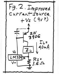
here we are, the mark 2 version. this time i've adopted a circuit first written about by Bob Pease back in 2000, in a column titled "What's All This Current Limiter Stuff, Anyhow?". it removes the V+/V- drop of the LM334 to outside of the current loop, using an external PNP transistor. in this configuration the set current is no longer given by I=68mV/R, but instead I=64mV/R. this is due to the V- pin current not going through the load (so i am led to believe).

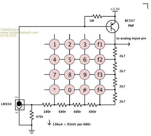
i've switched to a 140uA current, and use strings of 680r and 2k7 resistors. the 180r + 470r resistors in the circuit, plus the switch resistance (in my keypad this around 20 ohms) combine to make up the bottom '680r' resistor.

even when a key is not pressed there is still a current flow, corresponding to a non-existent key "20". this serves as a calibration point for the software. there are no fixed voltages specified in the code, just a ratio, with everything self-calibrating whenever no key is pressed. the design should be more than happy working down to the minimum Vcc of 2.3 volts.

here is the circuit:


and here is some test code:


SetPin 4, AIN
maxvolts = Pin(4)
SetTick 10, keyISR


Do
Do
Loop Until ready
Print Str$(inkey,2), Str$(keyvolts,6,3), Str$(maxvolts,6,3)
ready = 0
Loop


keyISR:
keyvolts = Pin(4)
inkey = Cint( keyvolts * 20 / maxvolts )
If inkey > 18 Then maxvolts = (0.995 * maxvolts) + (0.005 * keyvolts)
ready = 1
IReturn


note the line starting "If inkey > 18...", which implements the self-calibration when no key is pressed. the 0.995 and 0.005 have been chosen to allow for a relatively slow drift over a number of seconds, ignoring any rapid transients.

the only problem i have noticed is that if you hold your hand closely round the flex to the keypad, some jitter is present on the voltage fed back to the micromite. probably not an issue in a completed and boxed up project, but someone might like to have a closer look at this with a scope and see if it can be easily filtered out. going to a higher current may help, but then the current draw is now always present (even with no key pressed), so it is desirable to keep it as low as possible in case of battery operation.


enjoy,
rob :-)
 
Grogster

Admin Group

Joined: 31/12/2012
Location: New Zealand
Posts: 9044
Posted: 12:58pm 29 Mar 2014
Copy link to clipboard 
Print this post

Very nice.
Good job.
Smoke makes things work. When the smoke gets out, it stops!
 
WhiteWizzard
Guru

Joined: 05/04/2013
Location: United Kingdom
Posts: 2794
Posted: 01:45pm 29 Mar 2014
Copy link to clipboard 
Print this post

Hi Rob,

I really like this design, and want to build it right now but just realised I've not got any LM334's. So just ordered some on next day delivery but they won't be here till Tuesday morning thanks to it now being Sunday .

One question - Is there technically a way to 'store' the voltage output (i.e. the voltage on Pin 4 in your example), and whenever a 'significant' change occurs (i.e. a key pressed) then pulse an Interrupt to the uMite. Then remove the SetTick command so that the software is only responding to a key press rather than continually polling for one.

I am NOT saying this would be better - purely wondering if this is possible (as I was never any good at analogue electronics!).

Once again - a really nice design . . .

For everything Micromite visit micromite.org

Direct Email: whitewizzard@micromite.o
 
robert.rozee
Guru

Joined: 31/12/2012
Location: New Zealand
Posts: 2285
Posted: 05:25pm 29 Mar 2014
Copy link to clipboard 
Print this post

  WhiteWizzard said  
One question - Is there technically a way to 'store' the voltage output (i.e. the voltage on Pin 4 in your example), and whenever a 'significant' change occurs (i.e. a key pressed) then pulse an Interrupt to the uMite. Then remove the SetTick command so that the software is only responding to a key press rather than continually polling for one.


it would be technically possible (pretty much anything is), but would add to the circuit complexity. one could use a comparator along with a few other passive components to detect the drop created when a key is pressed. this output could then trigger an interrupt via a second (digital) input pin. but at that point one is using two pins, and a quantity of electronics that is fast approaching the complexity of a dedicated I2C keypad controller (or a second PIC). it was with great trepidation that i introduced the PNP transistor - the goal was to use the bare minimum of extra components.

for those interested, here is the original Bob Pease circuit. alas, Bob is no longer with us:


it makes for a great LED torch (Zl being a white LED) that is able to run with the battery voltage right down to within a fraction of the LED forward voltage using 3x AA batteries for the supply.

and i seem to have tracked down the source of the jitter i mentioned earlier. it was originating from my netbook power supply, and getting directly into the micromite. this explains quite a few odd things i have seen with the micromite's analog inputs. even with just a 220k pot strung between Vcc and ground (wiper onto pin 4) massive jumps in the A/D values are seen when pin 4 is touched by a hand:

with netbook running off plugpack:
1.444
0.029
1.845
0.000
1.715
0.000
1.588
0.000

with netbook running off batteries:
0.478
0.475
0.480
0.475
0.474
0.478
0.471
0.478

(sampling at 10mS intervals, approx 35k to ground at pin 4)


rob :-)
 
Print this page


To reply to this topic, you need to log in.

© JAQ Software 2024