
|
|
Forum Index : Microcontroller and PC projects : MX170 PCB Layout single sided
| Author | Message | ||||
centrex Guru Joined: 13/11/2011 Location: AustraliaPosts: 320 |
Hi Grogster I see Sprint has a free viewer, printer program which uses a .lay file extension will you be providing this file in the final wash up of the board. That is if members stop requesting additional items to be added or modified, could go on forever. regards cliff Cliff |
||||
vegipete Guru Joined: 29/01/2013 Location: CanadaPosts: 1085 |
Please nudge the 5v output trio, the ground trio and 3v3 output trio near PIC pins 14 & 15 to be on the same 0.1 inch grid as the rest of the "mini-shield" pins. You don't want to go down the *cough*duino route where a 50mil screw-up becomes a new standard. Visit Vegipete's *Mite Library for cool programs. |
||||
Grogster Admin Group Joined: 31/12/2012 Location: New ZealandPosts: 9082 |
I could do that easy. The reason for thru-hole 100n's was to make it easier for to build for those who do not like SMD. Any boards I was going to supply(if any) would have the three SMD parts pre-fitted. [Quote=TZA]I would change the silkscreen for the t-blocks slightly. On the bottom (pins 1-14) I would use four 3-way blocks and on the top five 2-way blocks. That IS a good idea, and I had not spotted that. Much neater to change them as you suggest. Maybe, maybe not. Will see if I can re-arrange for more space there. I can shoehorn an LED in for the 3v3 rail somewhere. 
Not an insane idea - will see if I can squeeze that in too. You are a fountain of ideas, ain't you, TZA?! (rhetorical!) Smoke makes things work. When the smoke gets out, it stops! |
||||
| Grogster Admin Group Joined: 31/12/2012 Location: New ZealandPosts: 9082 |
@ atmega8 - will upload a ZIP shortly, which will have ALL files in it, including the raw LAY6 file for Sprint Layout 6. Smoke makes things work. When the smoke gets out, it stops! |
||||
| Grogster Admin Group Joined: 31/12/2012 Location: New ZealandPosts: 9082 |
@ atmega8 - will upload a ZIP shortly, which will have ALL files in it, including the raw LAY6 file for Sprint Layout 6. @ centrex - Design by committee.  Something I always promised myself I would never get involved in, but here we are.... Still, despite that, some good ideas have been flowing. Perhaps the best one yet is atmega8's one - post the files, and then let people change the basic layout how they want - I think that is probably what I will now do. Something I always promised myself I would never get involved in, but here we are.... Still, despite that, some good ideas have been flowing. Perhaps the best one yet is atmega8's one - post the files, and then let people change the basic layout how they want - I think that is probably what I will now do.
@ vegipete - well spotted. Will nudge.
So, last round of changes, then I will upload a ZIP with all the files in it, and people can do whatever they want. Make it as-is or change it to suit themselves. I will probably still be getting some boards made, so if anyone wants any(with SMD fitted), then flick me a PM. Smoke makes things work. When the smoke gets out, it stops! |
||||
| paceman Guru Joined: 07/10/2011 Location: AustraliaPosts: 1329 |
Hi Grogs, a tiny suggestion - how about a 1K ohm on the Rx console input to protect against 5v USB to serial adapters? Greg |
||||
| Grogster Admin Group Joined: 31/12/2012 Location: New ZealandPosts: 9082 |
OK, will have to be SMD though. EDIT: No room. While I can fit one between the T-blocks and the chip, that does not cover you if you use the headers. I will upload ZIP shortly, and then let's call it quits! By all means, other members can download the layout, and change it to suit their purposes, as suggested by atmega8 - better then me changing things all the time. 
OK, here is the final: 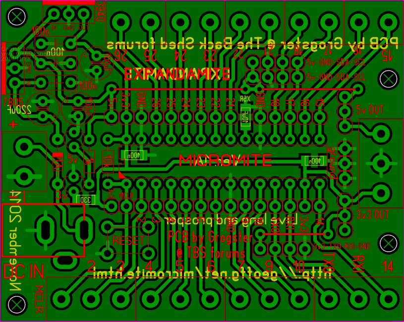
I've aligned the right-side t-block and headers for power, to a standard grid(0.3175), moved the 10k for MCLR slightly to the right to allow for IC socket, added 3v3 LED and resistor(SMD), and changed the terminal header to four-way, which is pin-compatible with the VT100 terminal board. Here is the ZIP file: 2014-11-13_011240_Expandamite_1A.zip This file contains all the gerbers, the Excellon drill data, the original LAY6 Sprint Layout file, the GIF image, and isolation milling CNC files.(mirror, drill from copper side, mill from bottom side, single pen(drill) size for holes as a pilot) Do with it what you will!!!! 
Smoke makes things work. When the smoke gets out, it stops! |
||||
| atmega8 Guru Joined: 19/11/2013 Location: GermanyPosts: 712 |
Grog, Thank you so much, for your "Open Source" PCB. Everyone must know that it takes hours over hours to develop a PCB. Also your PCB will help to distribute mmbasic to more People.. making it more public. THANK YOU !!!!!! ;-) |
||||
| Grogster Admin Group Joined: 31/12/2012 Location: New ZealandPosts: 9082 |
Danke. Bitte sch�n. (Thank you. You are welcome.) 
The Single-Sided concept was a bit limiting - I have got very quickly used to double-sided board work now!
But it was nice to be able to whip up a SS board again. Smoke makes things work. When the smoke gets out, it stops! |
||||
bigmik Guru Joined: 20/06/2011 Location: AustraliaPosts: 2870 |
Hi Grogs, Design by committee can be never ending.. I know you are near done BUT.. IF you add a pad on pin 28 of the pic you could then link it to the Vcc connection of the I2C for 3v3 operation and the 5v link can go the full distance. You still end up with 2 links but have the option of 3v3 or 5v i2c.. If you cannot juggle a bit then these links need to be insulated. Mick Mick's uMite Stuff can be found >>> HERE (Kindly hosted by Dontronics) <<< |
||||
| MicroBlocks Guru Joined: 12/05/2012 Location: ThailandPosts: 2209 |
I think there is even room to put 3.3v pins next to the 5v pins and have bot voltages available. :) :) Microblocks. Build with logic. |
||||
palcal Guru Joined: 12/10/2011 Location: AustraliaPosts: 1805 |
TZA wrote Grogster wrote @ Grogster I now use the low profile socket strip from Altronics for these connectors. I first bend the pins at right angles then solder to the board, much smaller than the vertical or right angle header. It is then just a matter of plugging in a row of header pins to the socket and connect the PicKit3. Paul "It is better to be ignorant and ask a stupid question than to be plain Stupid and not ask at all" |
||||
| Grogster Admin Group Joined: 31/12/2012 Location: New ZealandPosts: 9082 |
Can you please link me to those connectors, so I can check them out for future use? Smoke makes things work. When the smoke gets out, it stops! |
||||
| palcal Guru Joined: 12/10/2011 Location: AustraliaPosts: 1805 |
they are here header socket Paul Unfortunately on the Web you have to spend $20.00 with them to order. "It is better to be ignorant and ask a stupid question than to be plain Stupid and not ask at all" |
||||
| Grogster Admin Group Joined: 31/12/2012 Location: New ZealandPosts: 9082 |
Thanks, Paul.
On pricing for these boards, the best price is Itead using their 150 x 150 service, fitting four copies of the board to each of those 150 square boards. That's five 150 square boards for US$70 + freight, but I'll get 4 boards per 150 square PCB, so I will get 20 boards for the price. US$70 divided by 20 = US$3.50 per board + 1 20th of the freight charges, so I expect the boards to work out at about US$4 each, which I don't think is that bad. I will cut them up here and sand them square, fit the SMD for an extra $1, making the boards US$5 each including the SMD parts pre-fitted. It is then just freight charges depending on where and how it has to go. I will supply a BOM with each board, so people will know what they need to source at their end of things. Smoke makes things work. When the smoke gets out, it stops! |
||||
| bigmik Guru Joined: 20/06/2011 Location: AustraliaPosts: 2870 |
Gday Grogster, Give http://www.shenzhen2u.com a go. I used them for my, soon to be announced, MuP-Mini. I had the prototype done with them and some spacings were below their spec of 0.006" (I had 0.004" for my solder short pads) and they did a great job. I just ran your sizes through their calculator and you can get 10 off 15cm x 15cm for $56US (thats 40 Boards) and so far their postage has been around the $10 mark for `standard, i.e. 3-4week delivery, It may be a bit more for that size PCB so that would make 40 PCBs for around $70US delivered or $1.75 per PCB. I would however suggest that you make a small amount out of the deal for your troubles plus factoring in that you may not sell your entire stock. Also they have Vee Grooved all three batches of my boards so far (only 1 batch delivered so far, still 2 in the post). They send pictures of the boards in bubble shrink wrap before they ship them. They are not quick, about 1 week for the PCB and 3-4 weeks for standard delivery but they are cheap and I have been happy with the ones I have so far. Mick Mick's uMite Stuff can be found >>> HERE (Kindly hosted by Dontronics) <<< |
||||
| Grogster Admin Group Joined: 31/12/2012 Location: New ZealandPosts: 9082 |
Seems like very good price, and the reviews are also happy people, so I might give them a try. Three-to-four weeks lead time(including shipping) is what puts me off. I note that they offer a "Rush" service, but that brings the price up to US$91.25 before freight. With Itead, I generally have the boards inside two weeks max. I don't want to keep people waiting too long, or they will forget they even wanted one!
Still, I will give them(shenzhen2u) some thought. Smoke makes things work. When the smoke gets out, it stops! |
||||
| bigmik Guru Joined: 20/06/2011 Location: AustraliaPosts: 2870 |
Grogs, They also offer DHL shipping but it was around $25-$30 (you cant see the price till you upload files and do all the order basically) that should get it around 2weeks.. (still cheaper than iTead). Their `rush order' only saves a couple of days (on manufacturing time) and IMHO isnt worth it.. They Vee Grooved without me asking all 3 orders.. I just laid them out with 0.5mm separation and they did a Vee groove both sides. Obviously they are a new Company, I have orders No. 96, 120 and 127.. I have only received one lot so far that took about 3 weeks post.. The 2nd lot have been only 11 days so far and the 3rd lot only 3 days. They give you links to the boards like this one MuP-Minis In fact I found them because I couldnt get the tiny MuP-Mini made fairly cheaply (36 boards per panel) than from my usual suppliers or in fact at all because of the Number of boards per panel... Sitopway would do them but the cost was about 75c each US which was OK but I thought they should be cheaper than that. Regards, Mick Mick's uMite Stuff can be found >>> HERE (Kindly hosted by Dontronics) <<< |
||||
| Grogster Admin Group Joined: 31/12/2012 Location: New ZealandPosts: 9082 |
Interesting.... I might as well give them a try. Smoke makes things work. When the smoke gets out, it stops! |
||||
| centrex Guru Joined: 13/11/2011 Location: AustraliaPosts: 320 |
Hi Grogster I hope you take the attached pictures as a compliment to the excellant job you did with the expandamite. Below is my version using your layout. I use a very old program for board layouts, it is called Traxmaker, it was developed for windows from a dos based version. The board is close to your dimensions, all done to a 0.1 grid with a 25mil snap to. Unfortunately I do not have the special cap req for the 170 micro. Anyway here they are. 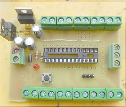
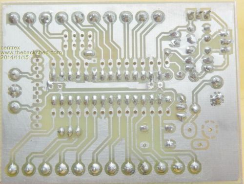
The board is made with Riston coated pcb, which is hard to get in Sydney as both sources are no longer... regards Cliff Cliff |
||||
