
|
|
Forum Index : Microcontroller and PC projects : Micromite MK2: MCP4822 DAC
| Author | Message | ||||
| matherp Guru Joined: 11/12/2012 Location: United KingdomPosts: 11564 |
The MCP4822 dual 12-bit DAC is my favorite for general purpose use (�2.09 from RS). It is an 8-pin chip available as a PDIP. It has an internal 2.048 volt reference and an optional gain of 1 or 2 allowing use from 0-2.048 volts or 0-4.096 volts (depending on VCC). It is very easy to drive with hardware SPI and is fast enough that no wait states would ever be needed driving it from the micromite. The attached demo program shows its use by linking the outputs of the DAC back to analogue channels on the micromite. Using a UA78M33CKCS voltage regulator to power the micromite I got the following output from the test program, you can see how the voltage from the DAC is limited by VCC when gain is set to 2: Gain = 1 Measurement resolution is 3.3/1024 = 0.003V DAC resolution is 2.048/4096 = 0.0005V DAC-A ADC DAC-B ADC 0.0000 0.0000 2.0000 1.9909 0.1000 0.0973 1.9000 1.8935 0.2000 0.2000 1.8000 1.7935 0.3000 0.2968 1.7000 1.6935 0.4000 0.3968 1.6000 1.5935 0.5000 0.4973 1.5000 1.4935 0.6000 0.5968 1.4000 1.3935 0.7000 0.6968 1.3000 1.2968 0.8000 0.7968 1.2000 1.1968 0.9000 0.8968 1.1000 1.0968 1.0000 0.9935 1.0000 0.9968 1.1000 1.0935 0.9000 0.8968 1.2000 1.1930 0.8000 0.8000 1.3000 1.2935 0.7000 0.6968 1.4000 1.3935 0.6000 0.5984 1.5000 1.4935 0.5000 0.4989 1.6000 1.5935 0.4000 0.3968 1.7000 1.6935 0.3000 0.2968 1.8000 1.7935 0.2000 0.1968 1.9000 1.8935 0.1000 0.1000 2.0000 1.9935 0.0000 0.0000 Gain = 2 Measurement resolution is 3.3/1024 = 0.003V DAC resolution is 4.096/4096 = 0.001V DAC-A ADC DAC-B ADC 0.0000 0.0000 4.0000 3.3000 0.2000 0.1973 3.8000 3.3000 0.4000 0.3978 3.6000 3.3000 0.6000 0.5968 3.4000 3.3000 0.8000 0.7968 3.2000 3.1930 1.0000 0.9968 3.0000 2.9941 1.2000 1.1946 2.8000 2.7935 1.4000 1.3946 2.6000 2.5968 1.6000 1.5935 2.4000 2.3968 1.8000 1.7935 2.2000 2.1968 2.0000 1.9876 2.0000 2.0000 2.2000 2.1871 1.8000 1.7968 2.4000 2.3849 1.6000 1.6000 2.6000 2.5871 1.4000 1.3968 2.8000 2.7871 1.2000 1.2000 3.0000 2.9871 1.0000 1.0000 3.2000 3.1871 0.8000 0.7968 3.4000 3.3000 0.6000 0.5973 3.6000 3.3000 0.4000 0.3968 3.8000 3.3000 0.2000 0.2000 4.0000 3.3000 0.0000 0.0005 ' MCP 4822 dual 12 bit DAC demo program ' cpu 48 option explicit option default FLOAT ' ' Pin assignments ' ' DAC pin 1 = VDD const cs=23 'DAC pin 2 connected to digital output on micromite ' Pin 25 = SCK : DAC Pin 3 ' Pin 3 = SDI : DAC Pin 4 const ldac=24 ' DAC Pin 5 connected to digital output on micromite const voutb=7 ' DAC Pin 6 connected to analogue input on micromite ' DAC Pin 7 = GND const vouta=6 ' DAC Pin 8 connected to analogue input on micromite ' 'Pin use ' setpin cs, dout setpin ldac, dout setpin vouta,ain setpin voutb,ain ' DIM gain as integer 'DAC output scale, can be 1 or 2, VDD to DAC must be at least 4.15V for gain 2 to use full output range ' dim DACa ,DACb dim voltage dim i as integer INIT: pin(cs)=1 'set chip select inactive pin(ldac)=1 'set ldac inactive spi open 5000000,0,16 '5 MEG, 16 bit transfer, CLK active high, data on leading edge ' MAIN: for gain=1 to 2 Print "Gain = ",gain print "Measurement resolution is 3.3/1024 = 0.003V" if gain=1 then print "DAC resolution is 2.048/4096 = 0.0005V" if gain=2 then print "DAC resolution is 4.096/4096 = 0.001V" print " DAC-A ADC DAC-B ADC" for i=0 to 20 voltage=i*gain*0.1 DACa=setdac(0,gain,voltage) DACb=setdac(1,gain,2*gain-voltage) print str$(DACa,1,4),str$(pin(vouta),1,4),str$(DACb,1,4),str$(pin( voutb),1,4) i=i+(0.1*gain) pause 500 NEXT i print "" next gain end ' ' Function to set output on one of the DAC channels ' function setdac (DAC as integer, dacgain as integer, volts) local dacdata as integer,FuncRet as integer dacdata=cint(volts * 2000 / dacgain) if dacdata>4095 or dacdata<0 or DAC<0 or DAC>1 or gain<1 or gain>2 then setDAC=0 exit function endif setdac= dacdata /2000 * dacgain if DAC=0 then dacdata=dacdata or &B0011000000000000 else dacdata=dacdata OR &B1011000000000000 endif if gain=2 then dacdata=dacdata and &B1101111111111111 'clear bit 13 to set gain of 2 pin(cs)=0 'enable data reception FuncRet=spi(dacdata) 'output the control bits and the data pin(cs)=1 'disable data reception pulse ldac,0.005 end function |
||||
| viscomjim Guru Joined: 08/01/2014 Location: United StatesPosts: 925 |
Hi Matherp, thanks for this code. This is a perfect little chip to use in my programmable power supply for adjusting voltage and current with the addition of just one little 8 pinner. Very cool. Thanks!!! |
||||
| matherp Guru Joined: 11/12/2012 Location: United KingdomPosts: 11564 |
Oops..... Function setdac should read: function setdac (DAC as integer, dacgain as integer, volts)
local dacdata as integer,FuncRet as integer dacdata=cint(volts * 2000 / dacgain) if dacdata>4095 or dacdata<0 or DAC<0 or DAC>1 or dacgain<1 or dacgain>2 then setDAC=0 exit function endif setdac= dacdata /2000 * dacgain if DAC=0 then dacdata=dacdata or &B0011000000000000 else dacdata=dacdata OR &B1011000000000000 endif if dacgain=2 then dacdata=dacdata and &B1101111111111111 'clear bit 13 to set gain of 2 pin(cs)=0 'enable data reception FuncRet=spi(dacdata) 'output the control bits and the data pin(cs)=1 'disable data reception pulse ldac,0.005 end function The program works as is but the function shouldn't need gain to be defined in the main program. Why can't I edit posts that have been replied to? Normal practice with code posts should be to edit the first listing so that readers don't need to trawl the whole thread to get the latest version. Best regards Peter |
||||
| G8JCF Guru Joined: 15/05/2014 Location: United KingdomPosts: 676 |
@matherp I think @gizmo said on another post recently, 'in the past some unscrupulous members have gone back in and edited their original posts after they have been replied to, in order to win their argument by amending the facts which they had originally posted' (I paraphrase). @Gizmo, could you further elaborate ? Peter The only Konstant is Change |
||||
| twofingers Guru Joined: 02/06/2014 Location: GermanyPosts: 1766 |
Hi Peter(matherp), first of all, thanks a lot for your code example. I think it would be great to have more from this, more code example on TBS. 
There is a very tiny bug in your Micromite code (sorry!  ): ):
function setdac (DAC as integer, dacgain as integer, volts)
this function setdac(DAC as integer, dacgain as integer, volts)
works better! 
I don't understand why I have to do this (multiplying with 2000): dacdata=Cint(volts * 2000 / dacgain)
?? This is my small MCP4822(SOIC), there also PDIPs available: 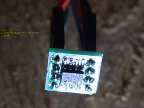
The MCP4822 is not only a dual 12Bit DAC, it's also a highly precise voltage reference. Really much better than I expected! Cheap and very easy to handle with our microcontrollers. I think about to use this DAC for programmable power supplys, signal generators, battery chargers, voice generators, current source � I converted your code for MAXIMITES (MMBasic 4.5D): '
' MCP 4822 dual 12 bit DAC demo program by matherp@TBS ' modified for Maximites MMBasic 4.5D (twofingers@TBS 2/2015) ' http://www.thebackshed.com/forum/forum_posts.asp?TID=7154&KW =4822 ' ' 4822-Registers ' A/B -- GA SHDN D11 D10 D9 D8 D7 D6 D5 D4 D3 D2 D1 D0 ' Bit 15 00 ' ' Provided AS IS without any warranty. ' Use it at your own risk. All information is provided for ' educational purposes only! ' ' Pin assignments on MCP4822 ' ' DAC pin 1 = VDD 3V3! With gain x2 and VDD 5V you will destroy your non 5V tolerant MM inputs!! cs =11 ' DAC pin 2 output(MM) SCK =12 ' DAC Pin 3 output(MM) SDI =13 ' DAC Pin 4 output(MM) ldac=14 ' DAC Pin 5 output(MM) voutb=3 ' DAC Pin 6 input(MM) ' DAC Pin 7 = GND vouta=2 ' DAC Pin 8 input(MM) RX =15 ' for SPI() ' 'Pin use ' ' CS, SCK, SDI, lDac can be any DOUT, RX any DIN SetPin cs, dout SetPin SCK, dout SetPin SDI, dout SetPin ldac, dout SetPin vouta,ain SetPin voutb,ain SetPin RX, din ' N/C, unused Dim gain Dim DACa ,DACb Dim voltage Dim i INIT: Pin(cs)=1 'set chip select inactive Pin(ldac)=1 'set ldac inactive MAIN: For gain=1 To 2 Print "Gain = ",gain Print "Measurement resolution is 3.3/1024 = 0.003V" If gain=1 Then Print "DAC resolution is 2.048/4096 = 0.0005V" If gain=2 Then Print "DAC resolution is 4.096/4096 = 0.001V" Print " DAC-A ADC -|- DAC-B ADC" For i=0 To 20 voltage=i*gain*0.1 DACa=setdac(0,gain,voltage) DACb=setdac(1,gain,2*gain-voltage) Print " "Format$(DACa,"%0.1f")" "Format$(Pin(vouta),"%0.3f")" -|- "; Print Format$(DACb,"%0.1f")" "Format$(Pin(voutb),"%0.3f") Pause 00 Next i Print "" Next gain ' Speedtest Dim a(2000) Timer=0 For i=1 To 2000 Next i Print Timer For i = 1 To 2000 a(i)=i/1000 Next i Timer=0 junk=0 For i=0 To 2000 SetdacA(a(i)) Next i Print Timer ' lets save some power Pause 2000 ShutDnDac(0) ShutDnDac(1) End '------------------------------------------------------- ' ' Sub to set DAC A channel, optimised for speed (~2000 op/sec) ' no error handling! Sub SetdacA(v) 'v=volt, DAC=A(or 0), Gain=2 Pin(cs)=0:junk=SPI(rx,SDI,SCK,v*1000 Or &B0001000000000000,,,16):Pin(cs)=1 Pulse ldac,0.005 End Sub ' ' Sub to shutdown the DAC 0 or 1 (A or B) ' Sub ShutDnDac(DAC) Local junk Pin(cs)=0 If DAC=0 Then junk=SPI(rx,SDI,SCK,&B0000000000000000,,,16) Else junk=SPI(rx,SDI,SCK,&B1000000000000000,,,16) EndIf Pin(cs)=1 Pulse ldac,0.005 End Sub ' ' Function to set output on one of the DAC channels ' Function setdac(DAC, dacgain, volts) Local dacdata, junk dacdata=Cint(volts * 2000 / dacgain) If dacdata>4095 Or dacdata<0 Or DAC<0 Or DAC>1 Or dacgain<1 Or dacgain>2 Then setDAC=0 Exit Function EndIf setdac= dacdata /2000 * dacgain If DAC=0 Then dacdata=dacdata Or &B0011000000000000 Else dacdata=dacdata Or &B1011000000000000 EndIf If dacgain=2 Then dacdata=dacdata And &B1101111111111111 Pin(cs)=0 junk = SPI(rx,SDI,SCK,dacdata,,,16) 'using defaults: speed=H (3 MHz), mode=3 Pin(cs)=1 Pulse ldac,0.005 End Function Download 2015-02-27_145157_MCP4822_MAXIMITE_DEMO.zip It's the first time I used SPI in my own code � and I will continue. It's fun! Regards Michael causality ≠ correlation ≠ coincidence |
||||
| matherp Guru Joined: 11/12/2012 Location: United KingdomPosts: 11564 |
The Dac is 12 bits i.e. 0-4095 and scales 0 to 2.048 volts (really 2.0475 volts) with gain = 1 So if I want 1.024 volts out I need to send the DAC 2048 1.024 * 2000 = 2048 |
||||
| twofingers Guru Joined: 02/06/2014 Location: GermanyPosts: 1766 |
Thanks! I thought that already, but I was not sure and the manual says nothing about that explicit (or I didn't find). All the better to be able to ask someone. Cool! 
causality ≠ correlation ≠ coincidence |
||||
| The Back Shed's forum code is written, and hosted, in Australia. | © JAQ Software 2026 |
